
The same LED is also used in the Adafruit circular ring LED (here a datasheet from Adafruit)
Get started
Where to start ?Well, first of all we NEED to have some kind of microcontroller in order to use these LEDs.
Powering up the LED is not enough, we need to "instruct" each single LED to lit with a specific intensity and color.
There are already many "tutorial" out there, for example Adafruit has some interesting one, like this one to use a Raspberry Pi for control, or this one for Arduino, but often these are just practical guides without explaining things in details.
Let see more in detail the LED specs and the protocol.
WS2812B connection
The LED strips, or the Adafruit ring, have a bunch of WS2812B LEDs connected in series.
They share the power supply and they are "chained" for the control signal.
Each WS2812B LED has a pin where to apply the control signal and one pin where the control signal is relayed out.
i.e. the control signal is NOT connected in parallel to all the LEDs.
This is extremely important to understand because each LED basically controls the others in the chain !
Here an image to describe this concept, from a datasheet.

The LEDs are chained and each LED basically regenerate the control signal for the other LEDs in the chain.
WS2812B protocol
So let see more in detail the protocol.
Each LED needs 24 bit of information (3 bytes) to determine if the LED is ON or OFF, what color and intensity.
The micro-controller has thus to send out a series of 24 bits, one for each LED in the chain.
So if the chain has 3 LED, the micro-controller will send out 24 x 3, i.e. 72 bit.
The first LED will use the first 24 bits and it will re-transmit to the other LED in the chain, the remains 48 bits.
The second LED in the chain will do the same so that the third LED in the chain will receive the last 24 bits.
This is important to know because the micro-controller NEEDS to know how many LEDs are in the chain.
Let see now more in detail some timing about this sequence.
The protocol is asynchronous, it means there is not an external clock.
There are though some specific times involved.
- Reset
A reset is intended if the data line remains low (0 volt) for more than 50 uSec (micro seconds).
A reset signal, i.e. keeping the signal line low for more than 50 uSec, is indicating to the LEDs when the sequence is terminated.
In the example of 3 LEDs chained, we'll need to have the reset sent every 72 bits. - Timing
The LEDs accepts a data speed of about 400 kHz. - Data
The data signal is not just set to +5V or 0 Volt to indicate 1 or 0.
A NRZ coding is used to prevent a series of "logical 0" to be interpreted as the reset signal.
See below for details
NRZ coding
NRZ stands for Non Return to Zero and is a way to encode data so that each bit, regardless the logical value 0 or 1, will have some time set to +5V (TH) and 0V (TL).TH + TL need to be around 1.25 uSec, what is change is the duty cycle.
The '0' will have less TH than TL but the sum of the two times will be as said, 1.25 uSec with a tolerance of +/- 600 nSec.
Specifically :
- '0'
- TH = ~0.35 uSec
- TL = ~0.9 uSec
- '1'
- TH = ~0.7 uSec
- TL = ~0.55 uSec
- Treset
- ~55 uSec
The micro-controller will have to generate for each bit that sequence.

WS2812B payload
Let see now the content of the 24 bits, i.e. how each LED can be controlled.
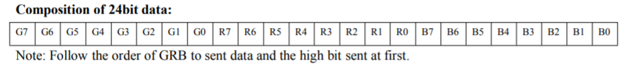
Basically there are 8 bit for each "color".
G for Green, R for Red, B for Blue.
Each color then can have 256 levels of intensity.
0 will be turned OFF, 255 decimal (0xFF hex) will be at maximum light.
So to have the LED all off, we'll have : 0-0-0
To have the White color, simply turn on all LEDs with the same value for each color.
For example to have the white color at the maximum intensity: 0xFF, 0xFF, 0xFF (or 0xFFFFFF)
If you want to dim that but still have the white : 0x50, 0x50, 0x50 (or 0x505050)
Microcontroller considerations
So at this point we have all the elements to write down some code to do control a WS2812B chain.
It is important to understand the limits of the platform (microcontroller) we choose and how to deal with the requirements.
For example an MSP430 launchpad can be a nice platform to play with and can be used with MspGcc or with Energia (similar to Arduino).
Note !!! It does exists a library for Arduino that handle these LEDs but the purpose of this article is to understand how to drive this thing.
If you want to use Energia note that it does exist also a library for Energia, so I'm not reinventing the hot water here :) .
It can be done also in C directly and of course the code CAN BE improved a lot !
Is just to give an idea about to do that from the scratch.
Shopping list
- MSP430 launchpad
- Energia
- Adafruit Ring.
Connection
Lets connect the Ring to the MSP430.
The ring is supposed to be powered at 5V but is working also at 3.3V.
So simply connect the ring to the Vcc, Gnd and we need a pin to be used as signal.
Let's use P1.0. In this way we can use the default LED to see activity.
Color table
We need to define first an alghorithm or something to decide about the colors.
There are many ways to do so.
For this simple example let start with a table with the basic colors.
Color
|
G
|
R
|
B
|
| Black | 0x00 | 0x00 | 0x00 |
| White | 0xFF | 0xFF | 0xFF |
| Green | 0xFF | 0x00 | 0x00 |
| Red | 0x00 | 0xFF | 0x00 |
| Blue | 0x00 | 0x00 | 0xFF |
So basically turning ON specific colors and with different intensity we can create every color we want, is only matter to know what color to use and how strong.
For this example we'll just use the table above. For more information about how to have colors take a look for example here.
Basic functions
We'll need some basic functions :
- writing a bit (0 or 1)
- sending out a reset
- preparing a sequence
- sending out the sequence
The basic brick is to be able to send out a single bit in NRZ coding.
The function will keep high and low the signal pin for the right amount of time.
A function will perform the reset forcing the signal line to 0 for more than 50 uSec.
Another function will prepare in a buffer the sequence of bits to send to the LEDs and another function will read the memory where the sequence is stored and will send it out using the writing bit function.
It is very important to be able to execute these function as fast as possible and with the correct timing, is possible maybe use some timer or interrupt for that.
Also to ensure speed is possible to evaluate to use some peripherals like USART (if available). Having an USART sending out the data maybe via DMA (or similar mechanism) can ensure a better result, assuming of course the USART can handle the NRZ.
Is really depends about what microcontroller is used.
Some considerations
This technology allows to do interesting things but there are limits to the number of LEDs in a strip.
Let's consider the 400 kHz version, it means that 1 LED will require something around 75 uSec to change state/color (1.25 uSec per bit x 24 = ~30 uSec to send the bits plus 55 uSec for the reset).
If you increase the number of LEDs to 10, will be something around 355 uSec (30 uSec x 10 + 55 uSec reset).
Let increase that number for 30 LEDs and we'll have 955 uSec, or 0.95 mSec.
If you have ONLY to control the LEDs is not a big deal, but if your micro-controller has other things to do, more time spent to control the LEDs is less time available to do other things.
Since the timing to control the LEDs is fixed, when the micro-controller is sending data to the LEDs can't do anything else.
Even better to disable interrupts while sending the sequences !
So for hobby is not a big deal but on real design is quite important to know the limits of this technology.
For example on complex system it make sense to have a small micro-controller devoted only to handle the LEDs, connected to the rest of the system with some high level protocol.
No comments:
Post a Comment