
 |
| The Infoglobe (from an adv) |
The idea is to use a modified Infoglobe to shows messages coming from other sources.
These notes are divided in different parts :
- possible applications
- the project
- let's open the Infoglobe
- modify the Infoglobe
Caution !
Modifying the Infoglobe, you will lose any guarantee on it.
Modifying the Infoglobe, you will lose any guarantee on it.
Exist also the potential to damage it and hurt yourself.
Possible Applications
It is possible to think about different possible uses for a modified Infoglobe capable to shows messages from the Home Automation system and the original purpose (Caller ID/Calendar/time).
Here some :
- display information/notifications from the system
- events notification (maybe adding also a sound alert), like a doorbell
- appointments/scheduling
- alarms
The idea is to modify an Infoglobe, in order to allow it to display messages coming from the Home Automation system or other sources.
In the Andrew R. Morris article, there is a description about how to temporarily disable the internal message generator (Caller ID/calendar/time/ecc.) and display different contents.
In his project, a PIC 16F84 micro controller is sending saved messages, driving a IR LED mounted close the original Infoglobe IR LED inside the base.
Starting from this idea, I developed an interface using a MSP430 micro controller from Texas Instrument, capable to drive the LED rotor.
Let's Open the Infoglobe
First of all I started from the Andrew R. Morris article which explain how to open and modify an Infoglobe.
The article starts explaining how to open the Infoglobe, that is not so easy if you mind to don't damage it, especially the plastic dome.
To open the Infoglobe, we will need :
- one small philips screwdriver, but long (the 4 holes for the screws are deep)
- a precision electronic screwdriver set
- one small long plier (to pick up some screws)
 |
The tools used to open the Infoglobe |
 |
| Note the 4 holes and the battery compartment |
Now, looking at the plastic dome close to the base, you can see 4 places where the plastic enter in the base.
Two places in the back and two places in the front, between the keyboard.
The article suggest to starts to leverage with a very small object (like a small flat screwdriver) on the right place of the keyboard, where you can see the dome entering in the base.Very very gently, try to force the dome out of the base, then as soon as the dome starts to come out, lever on the other point : the one on the left of the keyboard and then the two on the back.
Be careful to don't damage the dome, especially on the left side of the keyboard, since there is a safety micro-switch that cuts off power if the dome is removed.
Here a picture of the Infoglobe without the dome.
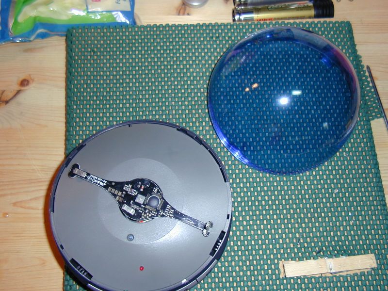
Now continue to remove the display arm.
It is screwed to the motor with 3 screws.
Here a picture of the display arm just removed.

It is possible now to remove the plastic protection, attached by the 4 screws on the base (we already removed them).It's enough to gently lever where the dome was inserted in order to remove the cover.
Here a picture of the circuit below :

At this point we can directly access the circuit in the base.
To remove totally the circuit is quite complicate and unnecessary for our purpose, also because in that case it is necessary to take apart the motor and pay attention of small wires.
The pcb is attached to the base with 3 screws.
Arrived at this point, we can start to modify the Infoglobe for our purpose (continue).
No comments:
Post a Comment