
Also to control the lights effects a PWM can be useful, so here some notes about to generate a PWM using the MSP430F2012.
A PWM signal is a digital signal with fixed frequency but varying duty cycle.

If the duty cycle of the PWM signal is varied with time, and the PWM signal is filtered, the output of the filter will be an analog signal.
Requirements
We mostly need a PWM signal, in order to drive the servo motor.
The exact data will be available only when we'll choose the servo motor, but generally speaking here some common characteristics of these objects.
A servo is basically a "block" with three wires.
Two for the power supply (usually between 4.8 to 6 V) and one needed to "feed" the control via a PWM signal.
The period of the signal usually is around 20 ms (50 Hz).
Wider pulses normally let move the shaft clockwise, thinner pulses let move the shaft counterclockwise.
Micro capabilities
To handle a PWM some resources are usually needed in a micro-controller.
We basically need a timer capable to work at the speed (frequency) we want.
i.e. the timer will generate the basic period (for example 20ms) and with some associated variables will be possible to "fire" an I/O pin to generate the signal.
For example, using a 8 bit variable, we can divide the generated frequency in "chunks" of 256 (8 bit = 256), so basically we can have 256 "steps" each one of 0.078125 ms (20 ms / 256 = 0.078125).
So, having such division, to generate a pulse of 2 ms, we will to keep an input high for approx 26 cycles of the timer (2 ms / 0.078125 ms = 25.6).
Increasing the division we can increase the precision of the generated pulses.
Experimental board
Here below is a test circuit to experiment about PWM.

The circuit is pretty simple.
We have two pushbutton, S1 and S2, that control the PWM.
- S1 - increment
- S2 - decrement
The micro need to be powered with a 3.3 V, so a regulator is needed.
Here a picture of the first prototype, made on a self powered breadboard.

Software
Using the timer of the MSP430F2012 (Timer_A) we generate a PWM signal.
The program is really simple. The timer is programmed and then a "dead loop" is entered, where we check the two push button.
Every time a pushbutton is pressed, we increase or decrease a variable that will be copied in the timer counter to generate the duty cycle.
This method is really simple and practical, but has some limits.
First of all, in the MSP430F2012 we have only 1 output we can use for the PWM.
In case to control more loads (like LEDs) we need more outputs.
Second, is difficult to generate a specific frequency.
So we used another way to generate the PWM.
We set up a timer so that count up to the value we want. Then we instruct the timer to generate an interrupt every time we reach that count.
In the interrupt we manually handle the PWM generation, using additional variables, driving directly one or more I/O pins.
The generated interrupt can be useful also to handle precise delays.
The circuit was built on a breadboard.
Different the goals to achieve with such test circuit :
- learn how to generate a PWM signal
- learn about the needs and behavior of the servomotor
Here the test circuit used for the experiments :
The two pushbutton allow to select different operating mode (see below).
Test circuit - the software
The goal of the test circuit (and software) is to experiment with the servomotor and put down the first design for the movement.
The two pushbuttons are used to set up different operations.
The S1 pushbutton is used to change the mode to work, the S2 pushbutton is used to execute the new mode to work.
The working modes, or "states" are :
- RESET
This is the default state. i.e. when the micro is turned ON, position itself in this state.
Pressing S2 force to load in the duty cycle variable the minimum allowed value for the servomotor, i.e. 36 equivalent to 380 uSec pulse length. - POSIT
This state acts as the final program to move the rangefinder at slow speed.
Every time the S2 pushbutton is pressed, the rangefinder is moved to the opposite position.
Two duty cycle values are reached :
- 78
Value for the initial position - rangefinder in vertical position - 161
value for the final position - rangefinder in horizontal position
The movement is "delayed", i.e. between every duty cycle increment or decrement, there is a delay, so to have a "slow" motion. - 78
- POSITOLD
Like the state before, but there is no delay in the movement.
The start and end positions are loaded immediately in the duty cycle variable, so the servomotor can reach the positions at full speed every time the S2 pushbutton is pressed.
- INCREMENT
Every time the S2 pushbutton is pressed, the duty cycle is incremented by 1 unit.
CAUTION ! There are no check on the servomotor limits ! - DECREMENT
Every time the S2 pushbutton is pressed, the duty cycle is decremented by 1 unit.
CAUTION ! There are no check on the servomotor limits !
These are "working" states.
- MOVINGUP
We reach this state from the POSIT state, when we want to increment the duty cycle.
The duty cycle is incremented by 1 unit, then a delay variable is initialized and the state is changed on the WAITINGUP state.
The delay variable is updated under interrupt.
When the duty cycle value reach the goal value (set in the POSIT state) the state is forced back in the POSIT one. - MOVINGDOWN
We reach this state from the POSIT state, when we want to derement the duty cycle.
The duty cycle is decremented by 1 unit, then a delay variable is initialized and the state is changed on the WAITINGDOWN state.
The delay variable is updated under interrupt.
When the duty cycle value reach the goal value (set in the POSIT state) the state is forced back in the POSIT one. - WAITINGUP
We reach this state from the MOVINGUP state.
In this state we wait that the delay variable, updated under interrupt, become zero.
When this happens, the code go back in the MOVINGUP state. - WAITINGDOWN
We reach this state from the MOVINGDOWN state.
In this state we wait that the delay variable, updated under interrupt, become zero.
When this happens, the code go back in the MOVINGDOWN state.
The up/down algorithm
The algorithm to control the up/down movement of the rangefinder, is based on a state machine.
This is needed in order to have a controlled slow movement.
The servomotor
Using the test circuit and software, we found out some characteristics of the servomotor used.
- The servomotor used is a Futaba S30031 servomotor.
General Specs:
- - Bearings: Standard
- - Gears: Standard
- - 60° speed: .23 sec @ 4.8v
- - 60° speed: .16 sec @ 6.0v
- - Torque: 44.40 oz/in @ 4.8v
- - Torque: 56.90 oz/in @ 6.0v
- -- 1.59 x.78x1.42 inches
- - 1.31 ounces
- The servomotor works nicely, even without the transistor, i.e. the microcontroller output enter directly in the servo control input.
At least at 5V there are no problems -
It works mainly on the length of the pulse, that must be between 380 uSec to 2.320 mSec, to cover the 120 degrees allowed by the servo gears. -
The frequency of the command pulse determine how fast the servo "execute" the movement and the "strenght" to retain the position. The default frequency used is 50 Hz because has the right speed and feedback speed. - We can mechanical mount the servo in the position we want and simply adjust the program to set the positions we need.
Now is time to illustrate the final hardware and software, with some extra features like the remote control.
The Hardware
Like the Servo control test circuit, the final circuit is based on the MSP430F2012 microcontroller.
Here the schematic of the final circuit :
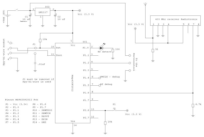
The pushbutton S1 remains to control the movement locally and/or test, but the command to move the arm is actually coming from the 433 Mhz receiver.
Like the previous test program, the servomotor is controlled by a PWM signal of 50 Hz with steps of .01 ms.
Here the built circuit with the connectors legend (right click on the image and choose "View image" to enlarge it) :

The circuit is built on a prototype board shaped round because the box we choose to attach inside the helmet.
There are two connector :
- the power supply (5.5 or 6V)
- the servomotor connector
In order to develop the software for this project, a development environment is necessary.
Here some necessary things :
- a computer with a free USB port
- a MSP430 IAR development system
- electronics tools (power supply/tools/oscilloscope)
On the test the rangefinder servomotor circuit.


The Software
- generate the PWM needed to position the arm
- recognize the incoming signal
The PWM generation
The PWM signal generation is based on the use of the internal timer of the MSP430F2012.
The timer is fed by the main clock frequency (MCLK = SMCLK = 16 Mhz).
Then one of the counter of the timer is loaded with the value 160, so basically to divide the incoming frequency by 160.
16 Mhz / 160 = 100 Khz, i.e. a signal with .01 ms as period.
The timer will generate so an interrupt every .01 ms.
Then another counter is used to "divide" the 100 kHz frequency in 2000 parts so to generate at the end the PWM 50 Hz frequency.
A third variable will basically handle the "duty cycle", i.e. how many of the 2000 parts when the output signal will be "high" and "low".
The PWM is based on a state machine.
Here the states :
- POSIT
This is the default state or starting state.
Every time the S2 pushbutton is pressed (or the RF signal is detected, the rangefinder is moved to the opposite position.
Two duty cycle values are reached :
- 78
Value for the initial position - rangefinder in vertical position - 161
value for the final position - rangefinder in horizontal position
The movement is "delayed", i.e. between every duty cycle increment or decrement, there is a delay, so to have a "slow" motion. - 78
- MOVINGUP
We reach this state from the POSIT state, when we want to increment the duty cycle.
The duty cycle is incremented by 1 unit, then a delay variable is initialized and the state is changed on the WAITINGUP state.
The delay variable is updated under interrupt.
When the duty cycle value reach the goal value (set in the POSIT state) the state is forced back in the POSIT one. - MOVINGDOWN
We reach this state from the POSIT state, when we want to derement the duty cycle.
The duty cycle is decremented by 1 unit, then a delay variable is initialized and the state is changed on the WAITINGDOWN state.
The delay variable is updated under interrupt.
When the duty cycle value reach the goal value (set in the POSIT state) the state is forced back in the POSIT one. - WAITINGUP
We reach this state from the MOVINGUP state.
In this state we wait that the delay variable, updated under timer interrupt, become zero.
When this happens, the code go back in the MOVINGUP state. - WAITINGDOWN
We reach this state from the MOVINGDOWN state.
In this state we wait that the delay variable, updated under timer interrupt, become zero.
When this happens, the code go back in the MOVINGDOWN state.
The RF recognition
The other thing the software has to do it to recognize when an RF command is received so to act a trigger for the arm movement.
The RF part is extremely simple and for that some work is required.
The RF Receiver is a hybrid module capable to receive a digital signal, using the carrier of 433 Mhz.
The module is designed to receive a frequency, not a simple on/off signal, so we have to assume a precise frequency as indication of triggering the arm, or ON condition, and the absence of this frequency as OFF condition.
So basically the idea is to connect a micro input pin to the RF receiver and have an interrupt when the signal goes from low to high.
Then, using the timer, every .01 ms we check that the input signal is what we expect.
If so, it is the frequency we decided is the ON condition, if not, will be the OFF condition.
Looking the above figure, the T0 event is the interrupt generated by the I/O pin.
After that, knowing the front of the wave was detected, every timer interrupt (the wave below represent the timer) we read the input line and we expect a determined amount of readings high and a determined amount of readings low.
If the count of readings high and low are as expected, then we have a valid signal.
If not, it means that another signal or just "noise" is present.
Here the states of the detection state machine :
- IDLE
This is the default state or starting state.
In this state nothing is done. Only the I/O interrupt can force a different state. - DETHIGH
In this state we try to verify that the signal that triggered the interrupt (T0) remains high for a number of reads.
Every .01 ms we read the signal and we check if the signal remains high for a specified number of cycles (timer interrupts).
(In the picture above, we expect to see the signal high in the T1 to T4 events)
If the signal remains high for the expected number of cycles, then we change state in DETLOW.
Otherwise we go in the DETEND state - DETLOW
In this state we try to verify that the signal that triggered the interrupt (T0) remains low for a number of reads.
Every .01 ms we read the signal and we check if the signal remains low for a specified number of cycles (timer interrupts).
(In the picture above, we expect to see the signal high in the T5 to T8 events)
If the signal remains low for the expected number of cycles, then we notify a Detect signal and then go in the DETEND state - DETEND
In this state, we wait for the next rise of the signal and then we re-enable the I/O interrupt
Here a state machine schematic, running under interrupt :
And here the flow of the state machine

Then there is another state machine, running in the main loop, with the purpose to "validate" the signal.
The detect state machine sometime can report a valid signal even in presence of noise.
In absence of signals, the receiver picks up anyway some "noise", and this noise can sometime have the same frequency of the valid signal, but for short time.
Because of that, a second state machine is in place, with some variables bonded to the interrupt timer, so to do some extra checks.
Here the states of the validate state machine :
- IDLE
This is the default state or starting state.
In this state nothing is done. To change state, the detect state machine have to issue a "signal detect" events. - VALIDATE
In this state we try to verify that the signal has a specific time presence.
i.e. a valid signal must be present for at least 15 ms.
If so, we change state in the WAITEND state, otherwise, if the signal is present less than 15 ms, we assume is not valid and return in IDLE state. - WAITEND
Before to issue the command to trigger the servomotor, we wait the end of the signal for at least 15 ms.
If this happens, we issue the command to start the servomotor, then we ignore any RF detection activity for at least 5 seconds, going the the IGNORE state. - IGNORE
In this state, we wait a specified amount of time, ignoring any RF activity.
When the time expire, we go back in the IDLE state
and here the flow chart.

The main loop
The software is based on two entities.
The main loop and the interrupts management.
The main loop is checking if the test pushbutton is pressed, handle the RF validation and the PWM settings.
Then there is the timer interrupt and the I/O interrupt (see above)

The timer interrupt take care executing the PWM indications set in the main loop and the RF detection.
The I/O interrupt starts the RF detecting sequence.
Measurements
In the gallery, some pictures from the oscilloscope.
- PWM signal generated for one position (800 uSec)

- PWM signal generated for one position (1660 uSec)

- RF detection - the upper trace is the signal coming from the receiver.
The signal is "noise".
The trace below is showing a debug signal, generated in the detection state machine.
Note how the debug spikes are ending with the signal, indicating a not recognized frequency

- RF detection - the upper trace is a valid signal coming from the receiver.
Note how the debug spikes are continuing also in the lower part of the signal, indicating a valid signal detected.

- Enlargement of the previous image


No comments:
Post a Comment