
 This can be an interesting project.
The idea is to use an old PSTN phone to control the user end of an entry phone system.
Different functionalities can be developed, this article is concentrated to the door opening one.
The idea is to interface the rotary dial of an old PSTN phone with a small MCU capable to decode a number composed with the rotary dial and activate a relay if a specific number is selected.
The rotary dial
The first thing to do is to understand how a rotary dial works.
The rotary dial is conceptually very simple, it is a switch that can be activated multiple times by a mechanic wheel.
The wheel is controlled by a spring so that the switch is activated automatically at a specific speed.
The wheel is controlled by a spring so that the switch is activated automatically at a specific speed.
Because the time when these devices were used and the mechanical part, there is not a specific universal standard for the rotary dial.
Basically every company and country did what they wanted, ending up with many variants.
Basically every company and country did what they wanted, ending up with many variants.
For example in USA was common to have a "pulse" long about 100 ms with a duty cycle of 60/40%, in Europe the pulse was up about 250 ms.
The number 1 was a single pulse, the number 2 two pulses, the number 3 three pulses and so on.
The 0 was 10 pulses.
Note that is possible also to have rotary dials with different "patterns", like 1 pulse for the number 0, 2 pulses for the number 1 and so on.
The 0 was 10 pulses.
Note that is possible also to have rotary dials with different "patterns", like 1 pulse for the number 0, 2 pulses for the number 1 and so on.
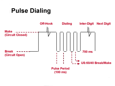 |
| Typical pulse timing in USA |
Between a series of pulse, it was considered a pause of 700 ms between digits.
This why in the end is better to wait at least 2 to 5 seconds before to consider the number formed.
This why in the end is better to wait at least 2 to 5 seconds before to consider the number formed.
As corollary, this means that is possible every rotary dial can end up with different pulse length and patterns.
Never assume every rotary dial behave in the same way, especially also because are mechanical devices and thus subject to wearing out and losing timing.
Never assume every rotary dial behave in the same way, especially also because are mechanical devices and thus subject to wearing out and losing timing.
The System
The idea is to use a small MCU arduino-like, something like the Trinket from Adafruit for example.
With an MCU will be possible to "read" the rotary dial and detect when a number is composed.
When the programmed number is "dialed" the MCU will activate the relay simulating the pushing of the button to open the door.
With an MCU will be possible to "read" the rotary dial and detect when a number is composed.
When the programmed number is "dialed" the MCU will activate the relay simulating the pushing of the button to open the door.
Let see a generic schematic block of the system :

The rotary dial is seen as a normal switch and thus is simply interfaced with some pull up/pull down to an I/O of the MCU.
An extra push button is added for the programming of the number.
Let's see a generic flow of operations we want to be performed.

The state machine is quite simple.
We have 5 states.
We have 5 states.
- Idle
- Detect
- Activate
- Deactivate
- Programming
Idle
The code starts in Idle.
In this state the relay is off and the system is reading the rotary dial input and the programming button.
In this state the relay is off and the system is reading the rotary dial input and the programming button.
If the programming button is pressed, the system goes in programming mode (see dedicate state machine).
The programming phase is needed to instruct the system to recognize a specific number.
So in programming mode the user press the push button, then compose a number using the rotary dial.
After few seconds of pause (let say 5 seconds) the system will store the recognized number to be used to control the relay.
So in programming mode the user press the push button, then compose a number using the rotary dial.
After few seconds of pause (let say 5 seconds) the system will store the recognized number to be used to control the relay.
If a signal is detected from the rotary dial, the state machine jumps to the Detect state.
Eventually also some kind of feedback will be used to inform the user of the completion of the programming phase and readyness, maybe activating the relay or adding a LED.
Detect
In this state the code is actively reading the rotary dial, storing the numbers detected.
After a pause of 5 seconds from the last reading it will be assumed the number to be complete and will be compared with the number stored during the programming phase.
After a pause of 5 seconds from the last reading it will be assumed the number to be complete and will be compared with the number stored during the programming phase.
If the numbers match, the state will change in the Activate state.
Activate
In this state the relay is activated and kept on for a fixed time (1 or 2 seconds) to simulate the pressing of the button to open the door.
When the timer expire will be forced the state of Deactivate.
Deactivate
In this state will be done a cleaning of timers and reset the state machine to Idle.
In the next article more details about the system.
No comments:
Post a Comment