
In this article we'll discuss about the way to communicate with the rotating arm of the Infoglobe.
Note: I developed this interface time ago, using the Texas Instrument eZ430-F2013 and the IAR demo environment.
In future I will eventually port the work under MSPGCC and different MSP430 processors (like the eZ430-RF2500).
First prototype
The first thing to do is to develop a little prototype based on the MSP430 family processor, for the first tests.
The chosen micro is the MSP430F2012, with the USB development system bought time ago.
The purpose of the first prototype is to develop a test code capable to generate the 38 kHz burst and the necessary timing.
IR Protocol
The first step is to handle the IR Transmission for the rotating arm.
Here a description of the protocol (from the Andrew article) :
Some basic data :
- the data are transmitted over a 38 kHz IR carrier
- only the zeros are sent
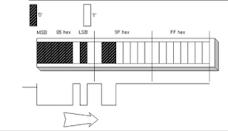
- every byte is sent MSB first
- the bit time is 1ms
- 1 ms 38 kHz burst is a logic '0', the absence of of signal for 1ms is a logic '1'

logic '0'= 1ms burst 38 kHz logic '1' - no IR signal
 |
Transmission example |
Only zeros are transmitted.
Bit time is 1mS.
A 1mS burst of 38 kHz is a zero, and no LED output for 1mS is a one.
The rotor can accept up to 35 text characters and 3 control characters.
The Infoglobe has 36 character slots, but reserves one slot for a space between the beginning and the end of the message.
Attempting to send 36 characters will blank the display.
The first character to be transmitted is a control character which tells the rotor new data is coming in and it has the following effects.
The numbers here are shown in HEX format.
The numbers here are shown in HEX format.
- 00
Loads the message into a buffer for the transition effects, but does not display it. 00 blanks the display unless the next character is also 00.
If the 00 is sent alone, the display goes blank, clearing the existing message in a scrolling blank.
It then displays and scrolls the previous message.
- 01
Loads the message for immediate display. Blanks the display if sent alone. - 02
Used when sending a stationary, front and center, flashing message. - 03
Causes the new message to scroll or not, the same as the previous message was doing. Blanks the display when sent alone.
- 04
Loads the message for immediate scrolling display.
Blanks the display if sent alone.
- 05
Overwrites a portion (or all) of an existing (scrolling) message with a flashing message. - 06
Toggles existing message scrolling on and off.
Ignores new message. Works the same if sent alone. Stops flashing if used to scroll a flashing display.
No other valid codes were found for the first byte.
Since the first 4 bits are always zero, meaning IR is emitted, the beginning of an incoming message is always detected. FFh, or the lack of IR emission signals the end of the incoming message. FFh has to be sent only if you’re sending one packet of information immediately after another. An example would be sending a scrolling, flashing message.
The second byte is the first message character when transition effects are not enabled.
To enable transition effects, both the first and second bytes must be 00.
The third byte will be the first message character.
To enable transition effects, both the first and second bytes must be 00.
The third byte will be the first message character.
When transition effects are not enabled, the last byte is the last message character.
When transition effects are enabled, the last character defines which effect will be used.
When transition effects are enabled, the last character defines which effect will be used.
There are 38 effects available, 00h to 25h.
They repeat at 80h to A5h.
This means that bit 7 of the effects byte can be high or low, but not bit 6.
The display goes blank when bit 6 is set.
They repeat at 80h to A5h.
This means that bit 7 of the effects byte can be high or low, but not bit 6.
The display goes blank when bit 6 is set.
All text characters are in 8 bit ASCII format.
Most of the ASCII text character set is supported except the following:
Most of the ASCII text character set is supported except the following:
% & + ; @ [ \ ] ^ _ ` { | } ~
01h through 1Ah appear to be foreign language characters.
20h through 24h are valid text characters, but they assume a different meaning when used as the last character in the string when transition effects are enabled. 80h and 81h are halves of the message icon (an envelope symbol) that is displayed when entering messages into the Infoglobe normally.
The timing of the transmission is very strict, since timing error accumulates with the message length.
You must adhere strictly to 8mS per byte.
At this time we want write a code to generate the 38 kHz signal and send characters.You must adhere strictly to 8mS per byte.
- bit 0 = 1ms burst 38 kHz
- bit 1 = 1ms empty
The test code is in C, using the IAR compiler :
IAR Embedded Workbench IDE
4.6B (4.6.2.0)
The compiler is embedded in the micro development kit MSP430F2013
Building notes
The first step is to choose and select on the microcontroller a clock speedy enough to generate and handle the required frequencies.
In the file msp430x20x2.h there are already defined registers and memory areas of the microcontroller, among them the calibration table for the internal clock generator.
Because the requested timing for this test, a 8 Mhz clock is OK.
The timer_A, available in the MSP430F2012 micro, can have different sources for the clock.
Since the generator clock module, by default, is generating the clock from the SMCLK signal, we will use it to feed the timer.
The SMCLK in the standard configuration, is identical to the system clock, in our example 8 Mhz.
So, in the initialization function we will set the clock for 8 Mhz, using the calibration table (the defines for the calibration values position are already present in the file msp430x20x2.h) :
/*
* Set DCO
* Setting the DCO to generate 5 Mhz clock source
*/
BCSCTL1 = CALBC1_8MHZ; // Set up 8 Mhz using internal calibration value
DCOCTL = CALDCO_8MHZ;
The timer will be set on the SMCLK signal and programmed to generate a 38 kHz signal.
The same frequency will be also used to obtain the 1 ms timing, needed for the bit length.
In order to generare the 38 kHz signal, we will need to set the timer for a double frequency, since the timer output will toggle every time the timer interrupt will trigger.
In other words we will need to set the timer to generate a frequency of 38 kHz * 2 = 76 kHz.
We will have a timer interrupt every 13 uSec.
In order to calculate a 1 ms timing, needed to set the bit length, we will use a counter inside the interrupt timer.
Every 76 interrupts (from 13 uSec) we will have 1 ms (13 uSec * 76 = 0.988 ms).
To have EXACTLY 1ms we should set the timer for 13.157 uSec.

The first test environment - the MSP430 plus USB dongle hooked up to the oscilloscope
Here some pictures of a scope, with some measurements on this test program :


The timing is not perfect, of course there is space for improvements.
But is a start.
The next step is to design and build the Infoglobe interface so to be able to control the rotating arm and be able to tune the timing to be compatible with the Infoglobe.
Software
Here the test program :
- Pin 1.0 (LED default test PCB) = 38 kHz burst di 1 ms.
i.e. 1ms pause, 1ms burst 38 kHz - Pin 1.1 - Timer_A generator -> 38 kHz
- Pin 1.4 - SMCLK, i.e. 8 Mhz
/** MSP430x2xx test38kHz Description: This code is to test a generation of 38 kHz burst
to be used to drive an Infloglobe
Author : Stefano Bodini
Update : May 2007
MSP430x2xx
-----------------
/|\| XIN|-
| | |
--|RST XOUT|-
| |
| P1.0|-->LED
| |
| P1.1|--> Burst out 38 kHz
| |
| P1.4|--> SMCLK
Built with IAR Embedded Workbench Version: 3.40A
*/
#include "msp430x20x2.h"
/*
* Functions prototype
*/
__interrupt void Timer_A (void); /* Timer A0 interrupt service routine */
void Init(void); /* Init LED */
/*
* Global defines
*/
/*
* Global variables
*/
static unsigned char t1ms_cnt;
static unsigned char send_bit;
/*
* Main entry file
*/
void main(void)
{
Init();
}
/*
* Init PWM Management - set timer
*/
void Init(void)
{
/*
* Set Watchdog
*/
WDTCTL = WDTPW + WDTHOLD; // Stop watchdog timer
/*
* Initialize Timer management variables
*/
t1ms_cnt = 0;
send_bit = 0;
/*
* Set I/O
* P1.0 -> I/O output - original LED on the board
* P1.1 -> Timer_A output - Out 0 - control IR LED
* P1.2 -> input - original frame from Infoglobe
* P1.4 -> output - SMCLK
*/
P1DIR |= 0x13; // Set P1.0 and P1.1 and P1.4 output direction
P1SEL |= 0x02; // Set P1.1 on OUT0
P1SEL |= 0x10; // Set P1.4 on SMCLK
P1OUT = 0; // Force out low
/*
* Set DCO
* Setting the DCO to generate 8 Mhz clock source
*/
BCSCTL1 = CALBC1_8MHZ; // Set up 8 Mhz using internal calibration value
DCOCTL = CALDCO_8MHZ;
/*
* Set Timer
* In SMCLK = 8Mhz
*/
CCTL0 = CCIE; // CCR0 interrupt enabled
TACTL = TASSEL_2 + MC_1; // SMCLK, up mode
TACCR0 = 105; // Approx 13uS (26uS / 2)
TACCTL0 |= 0x0080; // Enable Out0
_BIS_SR(LPM0_bits + GIE); // Enter LPM0 w/ interrupt
}
/*
* Timer A0 interrupt service routine
*/
#pragma vector=TIMERA0_VECTOR
__interrupt void Timer_A( void )
{
if(t1ms_cnt++ == 76) // 76 == 38 * 2
{
t1ms_cnt = 0;
send_bit ^= 1;
}
if(send_bit)
P1OUT ^= 0x01; // Toggle LED
else
P1OUT &= ~0x01;
}
I do have all the images but I see them on the blog site as well.
ReplyDeleteWrite me at thefwguy@apkh.org to see what you need, if I can I'm more than happy to share with you.