

In order to have more flexibility to put the encoder on panels, I usually manually wire it on a prototype board, every single time.
So it is time to have a standard way to deal with this.
Standardization
The first thing to do is to decide a standard way to use it in the projects.Here some requirements :
- Need to use the less possible number of wires
- Need to be easily mechanical connected on a panel
The encoder I use normally has 5 pins, 3 for the encoder and 2 for the switch so a total of 5 wires (similar to the ALPS EC11 series).
However, I normally use the ground as common, so I can have the encoder common and one pin of the switch connected to ground, thus 4 wires are enough.
Some capacitors and resistors are normally used on the encoder but they need to be close to the microcontroller, to clean up the signal, so normally they are placed on the main PCB for the project.
This leave the breakout a very simple and straightforward one.
The PCB will have a couple of holes to attach the PCB to a panel.
In the picture, an example of the way I used the encoders before this project :


The wiring in the example prototype uses 5 connections, two basically are to be connected to GND anyway.
In the picture, an example of the way I used the encoders before this project :


The wiring in the example prototype uses 5 connections, two basically are to be connected to GND anyway.
The circuit

A 4 pin header is connected to the encoder with this pinout :
- GND
- Encoder B
- Encoder A
- Switch
The header is soldered on the opposite side, to facilitate the panel mounting.
Note that usually the encoder needs additional components, resistors and capacitors.
I usually place them on the project PCB to have them close to the processor to better clean up the signal.
This is mostly a mechanical solution to have the encoder mounted on a panel.
Here a view of the PCB (component side)


Great quality, exactly as planned.
So immediately I did grab one PCB and mounted one of the encoders I had around (an ALPS) and the 4 pins header.
The only "problem" (my fault) is that the encoders, at least the ones I have around, have two small plastic pins coming out on the bottom to facilitate the orientation when mounting automatically.
So I had to cut them out from the encoder or .. as alternative, I could drill two small holes in the PCB.
I will see to modify eventually the PCB adding the two holes, but I fear is really depending about a specific model of encoder.
Anyway, no problem after cutting out the plastic pins to mount the encoder on the PCB.

To test it I just used the encoder to a project I'm completing and it works as expected !
Perfect !
Here step-by-step guide.

These the components used from LCSC and can be ordered together with the PCB :
Note that usually the encoder needs additional components, resistors and capacitors.
I usually place them on the project PCB to have them close to the processor to better clean up the signal.
This is mostly a mechanical solution to have the encoder mounted on a panel.
Here a view of the PCB (component side)

Building and testing
Finally the PCBs arrived !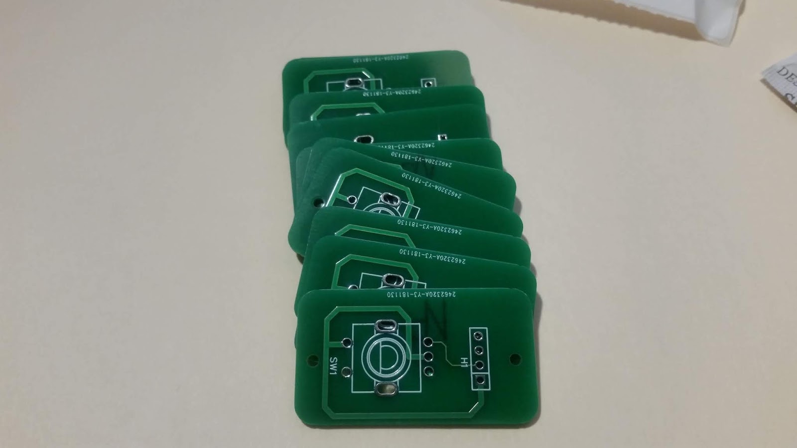
Great quality, exactly as planned.
So immediately I did grab one PCB and mounted one of the encoders I had around (an ALPS) and the 4 pins header.
The only "problem" (my fault) is that the encoders, at least the ones I have around, have two small plastic pins coming out on the bottom to facilitate the orientation when mounting automatically.
So I had to cut them out from the encoder or .. as alternative, I could drill two small holes in the PCB.
I will see to modify eventually the PCB adding the two holes, but I fear is really depending about a specific model of encoder.
Anyway, no problem after cutting out the plastic pins to mount the encoder on the PCB.

To test it I just used the encoder to a project I'm completing and it works as expected !
Perfect !
 |
| The encoder connected to the UV Box timer |
Ordering
Since I saved the project as public, is quite easy to order the PCBs and components.Here step-by-step guide.
- Open the project
- Scroll to Encoder-breakout-PCB and select Open in editor
(note, the image on the main page can be wrong, ignore it) - From the main menu, select Generate Fabrication File
(better to be logged in, you need an account to order anyway)

These the components used from LCSC and can be ordered together with the PCB :
No comments:
Post a Comment