This article is part of the MMCedu project (Magnetic Memory Core Education) and discusses about a keyboard to interact with the Magnetic Memory Core project.
Antefact
Eons ago, when I was at school learning how to write software, the first computer I used was an HP2000A.
In the morning, the first thing to do was to start the computer and it was quite a task, usually performed by a couple of students.
I had the "honor" to do the bootstrap duty quite some times.
The final goal was to load the operating system and start it and to do so, we had to write a short bootstrap code pushing some buttons.
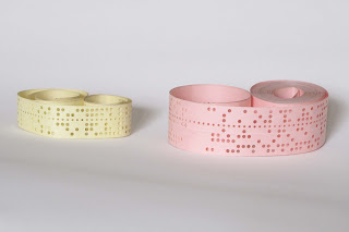
The bootstrap code was a series of octects words loaded one by one pushing on a row of buttons and once loaded did activate a punched tape paper reader, capable to read a punched tape containing the operating system.
 |
| Punched tape By TedColes - Own work, Public Domain, https://commons.wikimedia.org/w/index.php?curid=11736857 |
In order to enter the bootstrap code, we used a special "keyboard" with some illuminated pushbuttons.
The original bootstrap keyboard
 |
| HP2100 unit - main core for the HP2000A system http://computermuseum.informatik.uni-stuttgart.de/dev/hp2100/ |
Each button could show 1 bit. If set to zero the light was OFF, if set to 1 the light was ON.
There was a raw of 15 buttons grouped in 5 octects to write a "word" plus a bunch of other buttons for operations like read/write/reset/etc.
The bootstrap code was a bunch of octal numbers stored in the computer via the bootstrap keyboard.
The idea is to build an input keyboard to interact with the magnetic core memory kit, on the style of the HP2000A bootstrap keyboard.
Of course it will be different in many ways, let's just say the original HP2000A keyboard is just "inspirational" :)
The new style keyboard
First of all the new keyboard is designed to interact with the magnetic core demo circuit and it has these purposes :
- input data in the memory
- read/write
- select what byte to write/read
- show the content of the memory
Instead to use pushbuttons with lamps, I'll use pushbutons with LEDs plus a 32 bit matrix LED to show the content of the memory as a whole.
The input will use a 8 bit row of push buttons plus 5 other pushbuttons for write/read, reset and select what byte to write in the magnetic core memory.
Also a 32 LEDs will show the content of the memory when the button read is pressed.
4 LEDs will "point" to the byte to write (Address) controlled by the pushbuttons Prev and Next.
Pressing the reset buttons will erase the magnetic core memory, force the input to zero, set the address on the first byte and perform a read.
The result will be all the LED off with only the Address LED 1 lit.
Also a 32 LEDs will show the content of the memory when the button read is pressed.
4 LEDs will "point" to the byte to write (Address) controlled by the pushbuttons Prev and Next.
Operations - Reset
Pressing the reset buttons will erase the magnetic core memory, force the input to zero, set the address on the first byte and perform a read.
The result will be all the LED off with only the Address LED 1 lit.
Operations - Write
To write a byte in the memory :- input the value of the byte in the input row
- select with the Prev or Next buttons the final address
- push the Write button
A read operation will be performed automatically in order to refresh the Output matrix
Operations - Read
At any time, pressing the Read button, will force a read operation updating all 32 LEDs of the Output.
The byte selected will also be copied on the Input area.
Operations - Prev/Next
The two buttons select what byte of the 4 byte core magnetic memory is selected.When the selection reach an end, further pressing the button will not change the address.
i.e. pressing Next when the selection is on the last byte will not cause any change.
Only Prev will work.
On the same way, pressing Prev when the selection is on the first byte will not cause any change, only Next will work.
In the next article I'll describe the work to prepare the keyboard.


No comments:
Post a Comment