
Funny story of a trivial repair attempt over an electronic ballast used to drive a fluorescent UV bulb for an insect trap.
DISCLAIMER !!!
This stuff is connected DIRECTLY to the power grid and the fluorescent bulb emits dangerous UV !!
Working on these type of circuit REQUIRES knowledge and precautions !
DON'T ATTEMPT ANY REPAIR UNLESS YOU KNOW WHAT YOU ARE DOING !
The trap consist in a UV fluorescent bulb that is used to attract insects.
On the back of the lamp, there is an holder for cartridges that capture (glue) the insects.
As stated before, the UV emitted by the bulb CAN DAMAGE SKIN AND EYES.
Usually the bulb is not visible directly when the trap is put together, however in order to repair it, the bulb can be fully exposed and thus UV can reach you !
The problem
The lamp remains OFF when the trap is plugged in.
After opening the trap (5 screws to remove the rear cover) the circuit, an electronic ballast, is exposed.

A quick analysis shows the problem :

The two resistors are connected to the base of two MJE13003, a fast switching power transistor, very probably destroyed as well.
A repair would imply to :
- determine the original value of the resistors (impossible to read anything on a so damaged components)
- replace the burned resistors
- replace the two transistors MJE13003, as said they are very probably destroyed anyway
Diagnosis
- know the resistors value
- hoping the PCB will survive the component removal since the heat could make the traces to detach and the Bakelite to become brittle
- find the MJE13003 (is obsolete - not in production anymore)
Resistor value
Cutting one wire rather than desolder it, can prevent the resistor to fall apart if it is too much burnt out.
Sometime the burning can happens on the top but on the bottom some colored bands could be still readable.
 |
| One of the two resistors has at least a red band visible, so could be something starting with 2 |
 |
| This one is TOTALLY burned out |
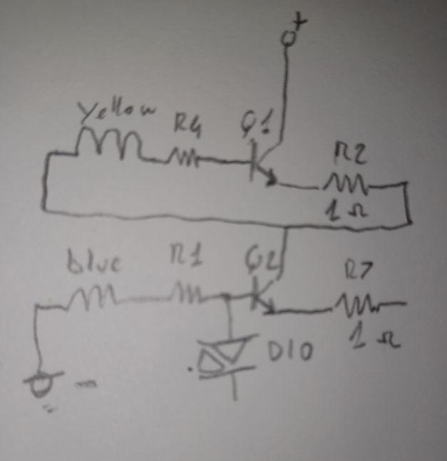
With that and the help of other people on the net I did find a schematic that is SIMILAR to the circuit to repair :

The used transistor in the schematic is the MJE13001 but it should be relatively safe to assume the same base resistor value, here placed to 20 Ohm 1/4 Watt (R5 and R2 on the schematic).
With some patience I was able to translate enough to compare with some schematics, this time based on the MJE13003.
PCB
 |
| The PCB in the PCB holder |
 |
| The damaged components. I would say the transistors are gone for good as well |
 |
| The traces are in a very good shape, a little bit change of color of the traces around the burned area, but they are not detaching from the Bakelite. |
Now let see the PCB component side after the removal
 |
| Lot of smoke dust, lets clean it up and see the PCB conditions |
 |
| Not bad. Q1 is where the damage is bigger, bad burn but didn't go through, the traces below are still in good conditions. |
In the last photo the damage around Q1 is clearly visible even after the clean up, sign that Q1/R4 generated a LOT of heat for quite long time.
Very possible on design .. so that one in the end is forced to buy a new unit.
For now I'll assume no other components are damaged.
The repair
I'm assuming that for such cheap circuits a 5% tolerance resistors are used, so 20/22 in the end is the same.
I did order some MJE13003 from China because this transistor is out of production for quite some time now (2013) and is not easy to found it at low cost elsewhere.
It doesn't make sense to spend more than 5$ each as I found on eBay for example !!!
I ordered 10 from China for about 4$, shipment included.
The usual suppliers (DigiKey, Mouser) doesn't have it anymore.
This means to wait some time before to receive them.
However looking in one of my junk boxes, I did find two ST13003, basically identical to the MJE13003 but from SGS.
The first attempt then will be using a couple of ST13003 and see if they survive.
Of course I'll use a new bulb as well since it is VERY probable the burnout happened for a discharge/short on the old bulb (burned out too).
Round 1
Capacitors, diode and coils and other resistors seems in perfect orders, where possible I did check them.
Thus the next step is to fix the DIAC with a new one.
Round 2
Also changing the DIAC nothing is working.
So this time the plan extend to :
- obtain the schematic (reverse engineering)
- remove again the transistors and verify they are still working, replace them with two tested MJE this time (now I have them)
- remove and change also the bridge (it implies to wait to receive a batch of new bridges)
- put the circuit in a test bench and VERY CAREFULLY, do some measurements
I want to see if at least the power arrives to the transistors and hopefully take also some measurements on the signals
I also ordered some 6.8 uF 250V capacitors. They "seems" OK but at this point I have to assume the major critical components were fried !
Round 3
Testing
Little bit more easier to dissipate the heat in the air rather than on the PCB for conduction.
The tests are done with the container open.
Also be VERY careful to don't touch anything when powered since the circuit is connected to the power line directly ! No transformer.
Comment
Economically speaking to repair this kind of circuits is simply trashing away money and time.
No comments:
Post a Comment