Translate

Showing posts with label HVAC. Show all posts

Saturday, April 20, 2019

HVAC connections

The "new" thermostat found in an antique mall


In an antique mall I did find a new (well, not really new) WiFi thermostat from Honeywell (Lyric T5), so I decided to change the current one I have at home ( a quite basic and simple one).


I think there is a "right way" to do things, so even for a trivial work like changing a thermostat, I find useful to document and explain what doing and why.


Saturday, July 7, 2018

Designing an HVAC monitoring system

Ideas - things to do

The HVAC (Heating, Ventilation and Air Conditioning) system, as many other systems, has the bad habit to broke down when most needed.

The idea is to design a monitoring system for HVAC capable to predict problems, with the less possible impact on the system, meaning that the monitoring system should be as much as possible independent from the HVAC itself.

Wednesday, October 8, 2014

Airflow sensor test

I used a little board with a MSP430-2013 and a LCD display  to develop the basic code to test and read the airflow sensor.

The circuit


Here a picture of the prototype


The software

The airflow sensor reading is based on counter and a timer.
The MSP430 pin connected to the airflow sensor is set in interrupt mode (rising) and after a check on the pin state to be sure is not a spike, a counter is incremented.
Every time a related timer expire, the value of the counter is copied into another variable (to be displayed) and the counter is reset.
I use another timer to display the read value on the display, after a integer-to-ascii conversion.
The code described is not reading the DS1820, only the airflow sensor.


Tuesday, September 9, 2014

Raspberry Pi - reading a DS18S20

One of the most common things for any embedded device is the capability to read temperatures.

Raspberry Pi doesn't has any ADC by default, so unless to hook one, the common way to read temperatures is via digital chips, like the DS 18S20.

The DS 18S20 is a 1-wire protocol chip-set from Dallas.
Fortunately somebody already wrote a bit banging support for the 1Wire protocol used by this chip-set , so it is only matter to connect the chip and enable some kernel modules to do so, at least in Raspbian (Wheezi).

I was able to duplicate the results described in the article RaspberryPI DS1820 without problems.
The example is based on a Perl script using the kernel services.

Here some my extra notes (I don't understand why so many people stopped to draw standard electronic schematics in favor of "cartoon" schematics).

Basic schematic to connect a DS1820 to the Raspberry Pi Gpio port.


Raspberry Pi GPIO pinout

DS1820 pinout


By default (as described in the article) the kernel module capable to handle the 1-Wire is disabled.
As first thing is necessary to enable it.


Open a terminal, then :
  • sudo modprobe wire
  • sudo modprobe w1-gpio  
  • sudo modprobe w1-therm

After that, to test if the DS1820 is ready and connected correctly :
  • cat /sys/bus/w1/devices/w1_bus_master1/w1_master_slave_count
The result should be the number of DS1820 connected.
To retrieve the serial number of the chip-sets :
  • cat /sys/bus/w1/devices/w1_bus_master1/w1_master_slaves
This is the Perl script used to read a sensor, copied from the article of David Mills,  RaspberryPI DS1820 (read that article for more details and how to read two sensors).

#!/usr/bin/perl
$mods = `cat /proc/modules`; 
if ($mods =~ /w1_gpio/ && $mods =~ /w1_therm/) 
{ 
   print "w1 modules already loaded \n"; 
} 
else  
{ 
   print "loading w1 modules \n"; 
   $mod_gpio = `sudo modprobe w1-gpio`; 
   $mod_them = `sudo modprobe w1-therm`; 
} 

$sensor_temp = `cat /sys/bus/w1/devices/10-*/w1_slave 2>&1`; 
if ($sensor_temp !~ /No such file or directory/) 
{ 
   if ($sensor_temp !~ /NO/) 
   { 
      $sensor_temp =~ /t=(\d+)/i; 
      $tempreature = (($1/1000)-6); # My sensor seems to read about 6 degrees high, so quick fudge to fix value  
      print "rPI temp = $tempreature\n";  
      exit; 
   } 
   die "Error locating sensor file or sensor CRC was invalid";  
}


Tuesday, August 26, 2014

Build an airflow sensor

For one of the projects I want/need to do, it was necessary to measure an airflow.
Here how I built a small sensor for that.

The simplest way to do so is to modify a computer fan.
I choose a small brush-less fan (for CPU), with ball bearings.

Circuit


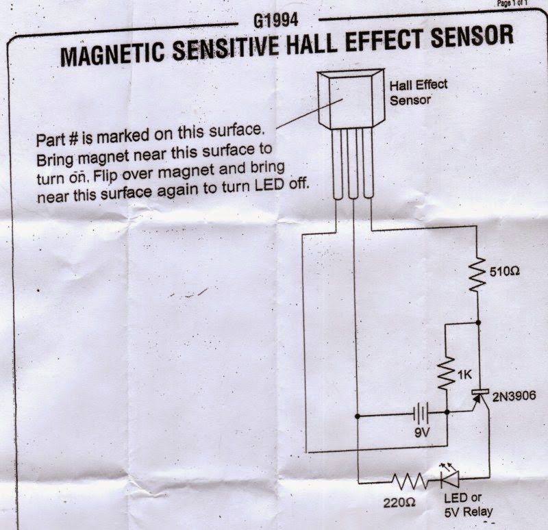
Probably the simplest and safest way to detect the rotation of the blade, is to use an Hall Effect sensor.
The sensor is placed inside the fan case, instead of the original motor circuit.
Below the bipolar Hall Effect sensor I used.  No really need to have a bi-polar Hall Effect, actually a single pole Hall Effect it would work better, but this is what I had around at the time.


Hardware preparation


The first step was to split the rotor from the  main case.
Usually there is a small groove that keep the rotor in place.
On the rotor, in this type of fan, there is the permanent magnet.
It need to be removed.

The motor is usually soldered to a PCB,  just stuck in the plastic case.
With some force is possible to disconnect it.
3 wires, as the original configuration of the fan, are required for the Hall sensor.
Vdd, GND and the output.

Here some pictures of the conversion, starting from the original CPU fan I used (below)


The first thing was to take it apart, removing the motor and electronic.


 Then I glued an Hall Effect sensor close to the shaft, on the base.


On the propeller, I attached two earth rare magnets (very small and very powerful), on the opposite sides.
I left the metal rim inside to facilitate the magnet attach (I also glued them) and to give a little bit weight to the propeller.


The magnets are attached with the poles in the opposite direction, because the Hall Effect sensor I used is a bipolar one, i.e. it needs to "see" a North/South pole change in order to go on, and a South/North pole change to go off.

Here the anemometer completed, attached to a simple circuit to test the Hall Effect sensor.


In the last picture, it is possible to see also the 1 wire temperature sensor  (DS18S20) connected to the cable.
It is the sensor needed to detect the temperature of the air flow.
A simple first prototype , using an MSP430-2013, it was built to develop and test the firmware to read the anemometer and the temperature sensor.