Translate

Showing posts with label hack. Show all posts

Sunday, April 11, 2021

X10 - AM486 - disable current sensing


At the time of the top usage of X10 there was lot of technical info on the net, today ... not so easy to find them.

I have to modify an old AM486 disabling the current sensing and I didn't find much around, so digging on my old notes here and some searches, I did come up with some info that I hope can be useful to others.


Sunday, May 5, 2019

Recycling an old toy

For some tests for a project I needed a moving base.
The ideal would be a robot, many kits are available now.
But before to spend money I wanted to see if some results were achievable and the quality of a camera.
So I did find an old toy made years before with my daughter and ...

Saturday, December 8, 2018

Infinity Disney base

Information about the Disney Infinity base.
Going around antique mall I bough few bases.
I'm collecting here some information, would be nice to be able to use the NFC reader for other purposes.

Tuesday, August 26, 2014

Build an airflow sensor

For one of the projects I want/need to do, it was necessary to measure an airflow.
Here how I built a small sensor for that.

The simplest way to do so is to modify a computer fan.
I choose a small brush-less fan (for CPU), with ball bearings.

Circuit


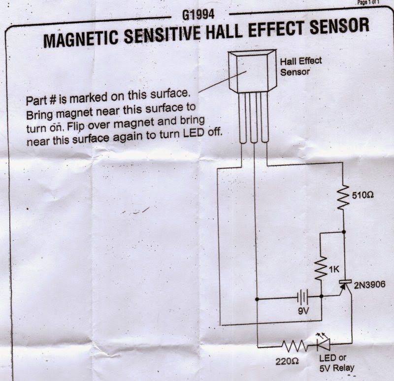
Probably the simplest and safest way to detect the rotation of the blade, is to use an Hall Effect sensor.
The sensor is placed inside the fan case, instead of the original motor circuit.
Below the bipolar Hall Effect sensor I used.  No really need to have a bi-polar Hall Effect, actually a single pole Hall Effect it would work better, but this is what I had around at the time.


Hardware preparation


The first step was to split the rotor from the  main case.
Usually there is a small groove that keep the rotor in place.
On the rotor, in this type of fan, there is the permanent magnet.
It need to be removed.

The motor is usually soldered to a PCB,  just stuck in the plastic case.
With some force is possible to disconnect it.
3 wires, as the original configuration of the fan, are required for the Hall sensor.
Vdd, GND and the output.

Here some pictures of the conversion, starting from the original CPU fan I used (below)


The first thing was to take it apart, removing the motor and electronic.


 Then I glued an Hall Effect sensor close to the shaft, on the base.


On the propeller, I attached two earth rare magnets (very small and very powerful), on the opposite sides.
I left the metal rim inside to facilitate the magnet attach (I also glued them) and to give a little bit weight to the propeller.


The magnets are attached with the poles in the opposite direction, because the Hall Effect sensor I used is a bipolar one, i.e. it needs to "see" a North/South pole change in order to go on, and a South/North pole change to go off.

Here the anemometer completed, attached to a simple circuit to test the Hall Effect sensor.


In the last picture, it is possible to see also the 1 wire temperature sensor  (DS18S20) connected to the cable.
It is the sensor needed to detect the temperature of the air flow.
A simple first prototype , using an MSP430-2013, it was built to develop and test the firmware to read the anemometer and the temperature sensor.


Sunday, August 28, 2011

Interface Roomba-USB

In order to diagnose/repair a Roomba, it is necessary to do some test and measurements.
Even if each Roomba has a diagnostic program on-board, often is necessary to have more control and a better feedback, with also some measurements.
To do so the basic tool every Roomba-hacker needs to have is a cable to connect the Roomba with a PC.

There are many ways to buy/build such cable.
This article describe how I did it, just to give ideas. Is not necessarily the best way but it worked for me.

Material


We started from a consumer SIM USB card reader.  These readers are available on ebay and similar places for few dollars.
Here a picture of the electronic board (they usually come in some kind of plastic box).


These USB SIM card readers usually are based on a chip capable to convert the USB port into a serial one, the Prolific PL-2303.
Then a cable with a minidin connector is needed and eventually a PCB minidin.
In my specific case I used :
  • USB SIM card reader
  • 8 pin minidin PCB outlet
  • 8 pin minidin cable (at both ends)

Preparation


The first thing to do is to remove from the USB SIM card some useless components, like the SIM card connector, a 74HC04 and a Crystal (3.5 Mhz).


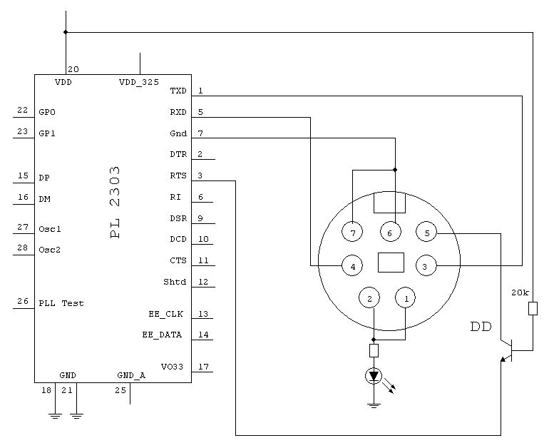
At this point is necessary to identify on the PL-2303 the pins we need to connect.
  • Pin 1 PL-2303
    TXD -> connected to the Roomba RXD (pin 3 minidin)
  • Pin 3 PL-2303
    RTS -> connected via a transistor to the Roomba Power pin (pin 6 minidin 7 - pin 5 minidin 8)
  • Pin 5 PL-2303
    RXD -> connected to the Roomba TXD (pin 5 minidin 8 - pin 4 minidin 8)
  • Pin 7 PL-2303
    GND - pin 6/7 minidin 7 - pin 7/8 minidin 8)

Here the schematic of what we want to do :


It is very important to pay attention of the type of minidin used.In the schematic I used the original Roomba minidin 7, so the pinout is DIFFERENT from the minidin 8 !
On the net is possible to find information about the pinout and specifications, like here.
Here some pictures of cable preparation.


Monday, August 22, 2011

CY7C68013A USB Logic Analyzer - Update

Time ago I received to test a little board based on the Cypress CY7C68013A and I wrote some notes about it.
This is a quick update of those notes.
These are informational notes only and are old!
I strongly suggest to buy the Logic package in order to have  the best results and easy operations.


usblogic_1.jpg

The CY7C68013A USB Logic Analyzer is a small board made by a Chinese company (Lcsoft) sold on Ebay from a China re-seller as a Logic Analyzer tool.
It's a small board based on a Cypress CY7C68013A micro-controller (an 8051 clone).

Exists a relatively easy hack in order to have the board working with Logic under Linux (tested with the 1.1.9 version under Ubuntu 11.04 quite time ago).

Here the hack :
  1. Be sure to don't have Logic running on the Linux  box
  2. Power on (plug-in) the Cypress CY7C68013A board
  3. Wait few seconds, the time for the board to start
  4. Remove the jumper J1
  5. Start Logic
After few seconds Logic will indicate ready to Start.
What happens is that without the jumper, Logic (at least the version 1.1.9) is loading the necessary firmware in the board and then start it.
Note that if you put back the jumper, all is working until you turn the board off and then back on or close Logic.
i.e. the firmware loaded is not permanent, every time it needs to be loaded.

I decided to put the board in a small box, for better protection and to be able to host a push-button.
Not having around any decent box, I temporary used two pieces of plexyglass. Ugly but functional :-)
I used a NC push-button, connected of course to the jumper J1.


Now in order to use the board with Logic, simply connect it to an USB port, then after few seconds, push the button and, while keeping it pushed, launch Logic.
When logic come out with Start, release the button and everything should work.

When closing Logic the configuration is lost, so it is necessary to un-plug the board  then plug the board back, following the procedure described above.
Much better to have an original Logic board.