The HP ProLiant DL360p Gen8 has 8 fans to cool down the two CPUs and other hardware.
These fans are high speed PWM controlled and are prone to fail over time.
The only thing to do is to replace the defective fan with a new one, but it would be nice to understand exactly what the problem is and check if the replacement fan is working before to open the server.
This article discuss some basic ways to generate a PWM signal using a MSP430.
Theory of operations
A PWM signal is a digital signal with fixed frequency but varying duty cycle.
If the duty cycle of the PWM signal is varied with time, and the PWM signal is filtered, the output of the filter will be an analog signal.
There are mostly 3 ways to generate a PWM signal using a MSP430 :
loop
timer
interrupt
Loop
The easiest way to generate a PWM signal is to create an infinite loop and inside the loop, set a I/O pin ON or OFF, using a counter to determine when to change the ON vs. OFF time, comparing it to a "dutycycle" value. Also in the loop must be present a delay to determine the frequency of the signal.
The pro is obvious, is really easy to generate a PWM signal in this way.
But there are big cons with this method.
Let see some of them:
all the resources of the processor are devoted to generate the signal
is extremely difficult to calculate a specific timing
any extra operation added in the loop go to alter the frequency of the generated signal
if interrupts are used the result signal is extremely instable
So the loop is not really something to consider for real use.
Timer
The second way to generate a PWM signal is to use a timer.
The MSP430 timer is capable to generate a PWM signal, it means that is possible to program a MSP430 timer specifically for the purpose to generate a PWM signal.
Because the signal in the end is generated by a piece of hardware, the result is extremely stable and precise.
Pro:
very stable PWM signal
extremely precise timing is possible
Cons:
the timer is devoted only to the PWM signal generation since the I/O pin is connected to it
only 1 PWM signal per timer is available
setting up the timer can be complicated
Interrupt
The third alternative is to soft-generate the PWM, like in the loop solution, but using a timer interrupt instead a deal loop.
A generic timer interrupt is generated and every time the interrupt is fired, a function handle one or more I/O pins to generate the PWM signal.
Pro:
stable PWM signal
precise timing (but less than the full timer solution)
possibility to have more than one PWM signals
possibility to use the timer resource for other purposes
easy to calculate the time
Cons:
limited timing range
PWM generated by a timer
Two MSP430 subsystems are involved in generating a PWM signal with the timer, the clock subsystem and the timer subsystem.
The output pin of the PWM signal, is directly connected to the timer.
Once programmed the timer, the generation of the PWM signal doesn't require any additional software.
Clock
The timer needs to be "fed" with a clock and there are different choices, depending the time required and the precision needed.
PWM using a generic time interrupt
In this way, a timer is still involved, but instead to generate the PWM signal, it generate interrupts.
Any time the interrupt is fired, a piece of software provide to change the state of an I/O pin depending some counter values compared with a threshold, generating in this way the PWM signal.
The frequency of the signal is determined by the timer setting and the precision is depending by the number of "steps" of the counter.
For example, if we want a 100 Hz signal, we need to set up an interrupt timing "at least" set to fire every 1/(100 Hz * 2) i.e. 0.005 seconds.
It means that every 0.005 seconds we have an interrupt and change the state of the output, obtaining a square wave of 100 Hz.
But we want to control the duty cycle, and so we need to have a smaller interrupt time.
Let say we want to divide our 100 Hz in 10 "steps", so we need to set the timer to fire every 1/(100 Hz/10) = 0.001 seconds or 1 ms.
Every ms we have an interrupt and then we decide if having the output ON or OFF.
Our period is so divided in 10 1 ms steps, i.e. 0.001 * 10 = 0.1 sec. that converted is 100 Hz.
But only 10 steps is not good, so better to split the time more, at least 50 or 100.
Of course we have some limits depending the input clock and how long the interrupt function requires to operate.
So we have to play with the clock in order to have the micro go faster and really optimize the interrupt function.
The interrupt function must be executed in a time much shorter than 1 ms, and we need to decide if the output is high or low depending a counter value in that timeframe.
Here a flow chart to better explain the basics.
On the left a flow of the main code.
It simply initialize the system and enter in an infinite loop. Eventually is possible to have code to perform settings/change of the parameters in the loop.
On the right the flow of the timer interrupt.
Every time the interrupt is fired, it uses a counter compared with a threshold to determine if turn the signal ON or OFF and then update the counter restarting the timer.
To measure exactly how long on average the function last, a debug signal is used.
The code turn this debug signal ON just after started the interrupt and OFF just before to exit.
With an oscilloscope is then possible to measure how long the signal remain ON. That more or less would be the time used by the interrupt function.
Here a couple of pictures from my oscilloscope during some tests.
Debug signal in the timer interrupt - DCO set for 16 Mhz selection.
The irregular wave indicates different execution timing, approx 3.5 us average execution time
PWM signal generated, 10 steps, approx 10Khz frequency - DCO set for 16 Mhz selection
This article describe in more detail the firmware that controls the lights for the RangeFinder.
The hardware
The hardware is very simple and is based on the MSP430F2012
Basically there are 3 LEDs connected directly to the micro controller.
With the resistors set to 220 Ohm (to increase the brightness) the circuit is consuming an average of 11-12 mA.
The Firmware
Like the servo motor control, the code is based on the PWM generation, one for each LED to control and on some state machines to control the effects.
Here the main state machine that control the lights effects :
States :
POSIT
This state is the default one.
When in this state, the code acquire the pattern to display (there are three istances of the state machine) and set up the next state, that can be MOVINGUP, MOVINGDOWN, ACTIVATE or RESTING, depending the value read in the pattern and the current value of the ducty cycle
MOVINGUP
This state is reached if the duty cycle need to be increased with a delay.
From this state is possible to go to the WAITINGUP or RESTING state.
MOVINGDOWN
This state is reached if the duty cycle need to be decreased with a delay.
From this state is possible to go to the WAITINGDOWN or RESTING state.
WAITINGUP
When in this state the code is waiting for the expiration of a counter decremented in the timer interrupt.
This state can only go in the MOVINGUP state
WAITINGDOWN
When in this state the code is waiting for the expiration of a counter decremented in the timer interrupt.
This state can only go in the MOVINGDOWN state
ACTIVATE
This state is reached if the duty cycle need to be adjusted without a delay.
From this state is possible to go to the RESTING state.
RESTING
When in this state the code is waiting for the expiration of a counter decremented in the timer interrupt.
This state can only go in the POSIT state
The main flow
The main flow is divided in two places :
the main loop
the timer interrupt
The Main Loop
The main loop handle the lights state machine.
The Timer interrupt
The timer interrupt, set to .01 ms, perform some operations, like the decrement of some delay variables (used in the light control state machine) and the PWM generator.
The pattern
Each LED is controlled by a "pattern", i.e. a series of numbers that define some characteristic of the effect.
Each "pattern" is composed by three values :
Duty Cycle
The first value is the duty cycle to reach.
The range of this value is between 0 and 2000, where 0 is no PWM output, and 2000 is full PWM output.
Speed
The second value indicate the "speed" needed to reach the duty cycle.
Each unit of speed represent 0.01 ms and the range is between 0 (maximum speed - no delay) and 65535 (delay of 0.6 seconds)
Resting
The third value indicate for how long the reached duty cycle need to be kept, before to pass to the next pattern.
Each unit of resting represent 0.1 ms and the range is between 0 (no resting) and 65535 (6 seconds).
In order to drive the servo motor for the Boba Fett project, a PWM (Pulse Width Modulation) is needed.
Also to control the lights effects a PWM can be useful, so here some notes about to generate a PWM using the MSP430F2012.
Theory of operations
A PWM signal is a digital signal with fixed frequency but varying duty cycle.
If the duty cycle of the PWM signal is varied with time, and the PWM signal is filtered, the output of the filter will be an analog signal. Requirements
We mostly need a PWM signal, in order to drive the servo motor.
The exact data will be available only when we'll choose the servo motor, but generally speaking here some common characteristics of these objects.
A servo is basically a "block" with three wires.
Two for the power supply (usually between 4.8 to 6 V) and one needed to "feed" the control via a PWM signal.
The period of the signal usually is around 20 ms (50 Hz).
Wider pulses normally let move the shaft clockwise, thinner pulses let move the shaft counterclockwise.
Micro capabilities
To handle a PWM some resources are usually needed in a micro-controller.
We basically need a timer capable to work at the speed (frequency) we want.
i.e. the timer will generate the basic period (for example 20ms) and with some associated variables will be possible to "fire" an I/O pin to generate the signal.
For example, using a 8 bit variable, we can divide the generated frequency in "chunks" of 256 (8 bit = 256), so basically we can have 256 "steps" each one of 0.078125 ms (20 ms / 256 = 0.078125).
So, having such division, to generate a pulse of 2 ms, we will to keep an input high for approx 26 cycles of the timer (2 ms / 0.078125 ms = 25.6).
Increasing the division we can increase the precision of the generated pulses.
Experimental board
Here below is a test circuit to experiment about PWM.
The circuit is pretty simple.
We have two pushbutton, S1 and S2, that control the PWM.
S1 - increment
S2 - decrement
The PWM output, can feed a transistor, so to be able to feed a load with full power (6V).
The micro need to be powered with a 3.3 V, so a regulator is needed.
Here a picture of the first prototype, made on a self powered breadboard.
Software
Using the timer of the MSP430F2012 (Timer_A) we generate a PWM signal.
The program is really simple. The timer is programmed and then a "dead loop" is entered, where we check the two push button.
Every time a pushbutton is pressed, we increase or decrease a variable that will be copied in the timer counter to generate the duty cycle.
This method is really simple and practical, but has some limits.
First of all, in the MSP430F2012 we have only 1 output we can use for the PWM.
In case to control more loads (like LEDs) we need more outputs.
Second, is difficult to generate a specific frequency.
So we used another way to generate the PWM.
We set up a timer so that count up to the value we want. Then we instruct the timer to generate an interrupt every time we reach that count.
In the interrupt we manually handle the PWM generation, using additional variables, driving directly one or more I/O pins.
The generated interrupt can be useful also to handle precise delays.
Test circuit - the hardware
The circuit was built on a breadboard.
Different the goals to achieve with such test circuit :
learn how to generate a PWM signal
learn about the needs and behavior of the servomotor
Here the test circuit used for the experiments :
The two pushbutton allow to select different operating mode (see below).
Test circuit - the software
The goal of the test circuit (and software) is to experiment with the servomotor and put down the first design for the movement.
The two pushbuttons are used to set up different operations.
The S1 pushbutton is used to change the mode to work, the S2 pushbutton is used to execute the new mode to work.
The working modes, or "states" are :
RESET This is the default state. i.e. when the micro is turned ON, position itself in this state.
Pressing S2 force to load in the duty cycle variable the minimum allowed value for the servomotor, i.e. 36 equivalent to 380 uSec pulse length.
POSIT This state acts as the final program to move the rangefinder at slow speed.
Every time the S2 pushbutton is pressed, the rangefinder is moved to the opposite position.
Two duty cycle values are reached :
78 Value for the initial position - rangefinder in vertical position
161 value for the final position - rangefinder in horizontal position
(note - these values can be changed, depending the physical mounting of the servomotor in the helmet)
The movement is "delayed", i.e. between every duty cycle increment or decrement, there is a delay, so to have a "slow" motion.
POSITOLD Like the state before, but there is no delay in the movement.
The start and end positions are loaded immediately in the duty cycle variable, so the servomotor can reach the positions at full speed every time the S2 pushbutton is pressed.
INCREMENT Every time the S2 pushbutton is pressed, the duty cycle is incremented by 1 unit.
CAUTION ! There are no check on the servomotor limits !
DECREMENT Every time the S2 pushbutton is pressed, the duty cycle is decremented by 1 unit.
CAUTION ! There are no check on the servomotor limits !
There are also other states, but they are not accessible via the S1 pushbutton.
These are "working" states.
MOVINGUP We reach this state from the POSIT state, when we want to increment the duty cycle.
The duty cycle is incremented by 1 unit, then a delay variable is initialized and the state is changed on the WAITINGUP state.
The delay variable is updated under interrupt.
When the duty cycle value reach the goal value (set in the POSIT state) the state is forced back in the POSIT one.
MOVINGDOWN We reach this state from the POSIT state, when we want to derement the duty cycle.
The duty cycle is decremented by 1 unit, then a delay variable is initialized and the state is changed on the WAITINGDOWN state.
The delay variable is updated under interrupt.
When the duty cycle value reach the goal value (set in the POSIT state) the state is forced back in the POSIT one.
WAITINGUP
We reach this state from the MOVINGUP state.
In this state we wait that the delay variable, updated under interrupt, become zero.
When this happens, the code go back in the MOVINGUP state.
WAITINGDOWN
We reach this state from the MOVINGDOWN state.
In this state we wait that the delay variable, updated under interrupt, become zero.
When this happens, the code go back in the MOVINGDOWN state.
The up/down algorithm
The algorithm to control the up/down movement of the rangefinder, is based on a state machine.
This is needed in order to have a controlled slow movement.
The servomotor
Using the test circuit and software, we found out some characteristics of the servomotor used.
The servomotor used is a Futaba S30031 servomotor. General Specs:
- Bearings: Standard
- Gears: Standard
- 60° speed: .23 sec @ 4.8v
- 60° speed: .16 sec @ 6.0v
- Torque: 44.40 oz/in @ 4.8v
- Torque: 56.90 oz/in @ 6.0v
-- 1.59 x.78x1.42 inches
- 1.31 ounces
The servomotor works nicely, even without the transistor, i.e. the microcontroller output enter directly in the servo control input.
At least at 5V there are no problems
It works mainly on the length of the pulse, that must be between 380
uSec to 2.320 mSec, to cover the 120 degrees allowed by the servo gears.
The frequency of the command pulse determine how fast the servo
"execute" the movement and the "strenght" to retain the position.
The default frequency used is 50 Hz because has the right speed and feedback speed.
We can mechanical mount the servo in the position we want and simply adjust the program to set the positions we need.
The final controller
Now is time to illustrate the final hardware and software, with some extra features like the remote control.
The Hardware
Like the Servo control test circuit, the final circuit is based on the MSP430F2012 microcontroller.
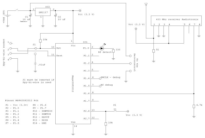
Here the schematic of the final circuit :
The pushbutton S1 remains to control the movement locally and/or test, but the command to move the arm is actually coming from the 433 Mhz receiver.
Like the previous test program, the servomotor is controlled by a PWM signal of 50 Hz with steps of .01 ms.
Here the built circuit with the connectors legend (right click on the image and choose "View image" to enlarge it) :
The circuit is built on a prototype board shaped round because the box we choose to attach inside the helmet.
There are two connector :
the power supply (5.5 or 6V)
the servomotor connector
The environment
In order to develop the software for this project, a development environment is necessary.
Here some necessary things :
Here some pictures of the environment (the laptop is running the MSP430 development software).
On the test the rangefinder servomotor circuit.
The Software
The software has two things to do :
generate the PWM needed to position the arm
recognize the incoming signal
The PWM generation
The PWM signal generation is based on the use of the internal timer of the MSP430F2012.
The timer is fed by the main clock frequency (MCLK = SMCLK = 16 Mhz).
Then one of the counter of the timer is loaded with the value 160, so basically to divide the incoming frequency by 160.
16 Mhz / 160 = 100 Khz, i.e. a signal with .01 ms as period.
The timer will generate so an interrupt every .01 ms.
Then another counter is used to "divide" the 100 kHz frequency in 2000 parts so to generate at the end the PWM 50 Hz frequency.
A third variable will basically handle the "duty cycle", i.e. how many of the 2000 parts when the output signal will be "high" and "low".
The PWM is based on a state machine.
Here the states :
POSIT
This is the default state or starting state.
Every time the S2 pushbutton is pressed (or the RF signal is detected, the rangefinder is moved to the opposite position.
Two duty cycle values are reached :
78 Value for the initial position - rangefinder in vertical position
161 value for the final position - rangefinder in horizontal position
(note - these values can be changed, depending the physical mounting of the servomotor in the helmet)
The movement is "delayed", i.e. between every duty cycle increment or decrement, there is a delay, so to have a "slow" motion.
MOVINGUP We reach this state from the POSIT state, when we want to increment the duty cycle.
The duty cycle is incremented by 1 unit, then a delay variable is initialized and the state is changed on the WAITINGUP state.
The delay variable is updated under interrupt.
When the duty cycle value reach the goal value (set in the POSIT state) the state is forced back in the POSIT one.
MOVINGDOWN We reach this state from the POSIT state, when we want to derement the duty cycle.
The duty cycle is decremented by 1 unit, then a delay variable is initialized and the state is changed on the WAITINGDOWN state.
The delay variable is updated under interrupt.
When the duty cycle value reach the goal value (set in the POSIT state) the state is forced back in the POSIT one.
WAITINGUP
We reach this state from the MOVINGUP state.
In this state we wait that the delay variable, updated under timer interrupt, become zero.
When this happens, the code go back in the MOVINGUP state.
WAITINGDOWN
We reach this state from the MOVINGDOWN state.
In this state we wait that the delay variable, updated under timer interrupt, become zero.
When this happens, the code go back in the MOVINGDOWN state.
Here a schematic of the PWM state machine
The RF recognition
The other thing the software has to do it to recognize when an RF command is received so to act a trigger for the arm movement.
The RF part is extremely simple and for that some work is required.
The RF Receiver is a hybrid module capable to receive a digital signal, using the carrier of 433 Mhz.
The module is designed to receive a frequency, not a simple on/off signal, so we have to assume a precise frequency as indication of triggering the arm, or ON condition, and the absence of this frequency as OFF condition.
So basically the idea is to connect a micro input pin to the RF receiver and have an interrupt when the signal goes from low to high.
Then, using the timer, every .01 ms we check that the input signal is what we expect.
If so, it is the frequency we decided is the ON condition, if not, will be the OFF condition.
Looking the above figure, the T0 event is the interrupt generated by the I/O pin.
After that, knowing the front of the wave was detected, every timer interrupt (the wave below represent the timer) we read the input line and we expect a determined amount of readings high and a determined amount of readings low.
If the count of readings high and low are as expected, then we have a valid signal.
If not, it means that another signal or just "noise" is present.
Here the states of the detection state machine :
IDLE
This is the default state or starting state.
In this state nothing is done. Only the I/O interrupt can force a different state.
DETHIGH In this state we try to verify that the signal that triggered the interrupt (T0) remains high for a number of reads.
Every .01 ms we read the signal and we check if the signal remains high for a specified number of cycles (timer interrupts).
(In the picture above, we expect to see the signal high in the T1 to T4 events)
If the signal remains high for the expected number of cycles, then we change state in DETLOW.
Otherwise we go in the DETEND state
DETLOW In this state we try to verify that the signal that triggered the interrupt (T0) remains low for a number of reads.
Every .01 ms we read the signal and we check if the signal remains low for a specified number of cycles (timer interrupts).
(In the picture above, we expect to see the signal high in the T5 to T8 events)
If the signal remains low for the expected number of cycles, then we notify a Detect signal and then go in the DETEND state
DETEND
In this state, we wait for the next rise of the signal and then we re-enable the I/O interrupt
Here a state machine schematic, running under interrupt :
And here the flow of the state machine
Then there is another state machine, running in the main loop, with the purpose to "validate" the signal.
The detect state machine sometime can report a valid signal even in presence of noise.
In absence of signals, the receiver picks up anyway some "noise", and this noise can sometime have the same frequency of the valid signal, but for short time.
Because of that, a second state machine is in place, with some variables bonded to the interrupt timer, so to do some extra checks.
Here the states of the validate state machine :
IDLE
This is the default state or starting state.
In this state nothing is done. To change state, the detect state machine have to issue a "signal detect" events.
VALIDATE In this state we try to verify that the signal has a specific time presence.
i.e. a valid signal must be present for at least 15 ms.
If so, we change state in the WAITEND state, otherwise, if the signal is present less than 15 ms, we assume is not valid and return in IDLE state.
WAITEND Before to issue the command to trigger the servomotor, we wait the end of the signal for at least 15 ms.
If this happens, we issue the command to start the servomotor, then we ignore any RF detection activity for at least 5 seconds, going the the IGNORE state.
IGNORE
In this state, we wait a specified amount of time, ignoring any RF activity.
When the time expire, we go back in the IDLE state
and here the flow chart.
The main loop
The software is based on two entities.
The main loop and the interrupts management.
The main loop is checking if the test pushbutton is pressed, handle the RF validation and the PWM settings.
Then there is the timer interrupt and the I/O interrupt (see above)
The timer interrupt take care executing the PWM indications set in the main loop and the RF detection.
The I/O interrupt starts the RF detecting sequence.
Measurements
In the gallery, some pictures from the oscilloscope.
PWM signal generated for one position (800 uSec)
PWM signal generated for one position (1660 uSec)
RF detection - the upper trace is the signal coming from the receiver.
The signal is "noise".
The trace below is showing a debug signal, generated in the detection state machine.
Note how the debug spikes are ending with the signal, indicating a not recognized frequency
RF detection - the upper trace is a valid signal coming from the receiver.
Note how the debug spikes are continuing also in the lower part of the signal, indicating a valid signal detected.
Time ago a friend of mine, Molly, asked me to help her to prepare some electronic effects for a costume : Boba Fett from Star Wars.
At the time I prepared some articles to document the work.
Here the material I prepared, edited for the blog. This is the first article, others will follow.
Introduction
Basically there was two areas of the costume where I helped :
Rangefinder movement
Rangefinder lights effects
Rangefinder
The rangefinder is, in the character fiction, a device capable to identify and point a target.
Physically is a funny shaped box, with some flashing lights and a screen, mounted on the top of a rod/pole, on the side to the helmet.
When not in use it rest vertically. When in use it is lift down in front to the visor.
There are two flashing lights in front and a "screen" in the back of the rangefinder, just in front of the visor.
The lights are turned on when the rangefinder is lifted down.
Lights
The rangefinder has three lights, supposedly going on when in the horizontal position.
Two flashing lights in front and one green or white light inside, in order to simulate the light from a monitor screen .
It is possible to design different circuits capable to drive the lights.
simple
classic
flexible
Simple
The circuit is quite simple and "classic" and can even be minimized using special components, like this :
The circuit is extremely simple.
A 3V coin battery to power supply 3 LEDs and a tilt switch turn on the LEDs when the rangefinder is horizontal.
Two of them will be "flashing LED", i.e. LED with already included an oscillator, like this one found on AllElectronics.
Pros :
very very simple
not critical
doesn't even need a PCB
Cons :
the flashing LEDs can not be controlled
battery can not last long
Classic
Alternatively, is possible to build an astable oscillator, using a couple of transistor, so to have the LEDs flashing alternatively and not in "simil sync" as the previous circuit.
Adopting an astable oscillator is little bit more complicated and it require a PCB (a piece of sperimental board is ok).
Something like that :
The circuit seems more complicated but is really not.
Is a "classic" astable multivibrator based on two transistor NPN who drive two normal LEDs (D1 and D3).
D2 is a green or light LED.
Pros :
the flashing LEDs are controlled
the battery can last longer
probably is the circuit used on the "original" costume
Cons :
require a little PCB to host the components
require little bit more work to be done
Flexible
The third way to drive the LEDs is, for my taste, the better.
Using a microcontroller, we can achieve the maximum about flexibility and an easy to program and change effects.
The hardware is very very simple, based on a MSP430F2012 microcontroller.
Simply we can connect the three LEDs to the micro I/O ports using the micro PCB.
After that is only matter to write a simple firmware capable to drive the LEDs.
It is quite easy to set up any pattern and also include some special effects on the one that simulate the screen.
The 3 LEDs will be connected to 3 I/O pin, programmed in output mode.
Another pin will be used to connect the tilt switch.
The tilt switch is not used to power supply the micro, because is not capable to give a neat on/off signal.
In this way the micro will read the tilt switch, acting also as filter.
When the tilt switch will indicate a off position, the micro will be placed in low power mode.
Pros :
the flashing LEDs are controlled
possibility to create many effects, even using PWM to control brightness
Cons :
require a little PCB to host the components
require little bit more work to be done
the battery life is not high
Movement
The rangefinder is attached to the helmet.
Since the goal is to have it moving automatically, from the vertical position to the horizontal one, a motor and gears will be needed.
The main challenge for the mechanic part, is the dimension and the torque needed to move the rangefinder.
Because the dimension, some limits will exist :
motor/gears The motor and the gearbox necessary to increase the torque, trading away the speed, must be small as possible.
power supply
For the same reason, the motor and the circuit will need to operate using the smallest possible amount of batteries.
The space in the helmet is not big
electronic
The motor need to be driven by an electronic circuit, capable to run it in both directions and possibly with different speed.
Also the electronic should be small as possible.
no wires Any necessary wire should be hide as much as possible.
So for example, the rangefinder lights will be self enclosed in the top box
The same for the motor control. Because of that, a remote control will be included so to activate the motor remotely.
The Rangefinder is placed on the top of a rod, connected to the helmet.
Usually is in vertical position but can be lowered in the horizontal position.
The idea is to make the Rangefinder move from vertical to horizontal, and back, automatically. The electronic to control the movement, will be based on a MSP430F2012 Texas Instrument microcontroller plus other components.
Like the lights, there are different possible choices.
The first is to use a normal DC motor, coupled with some gears.
The second, the one we adopted, uses a servocontroller.
DC motor
Servo
DC Motor
A RF receiver will provide the input for the microcontroller (a Texas Instrument MSP430F2012), that will drive a H bridge capable to power the DC motor in both directions.
The DC motor, geared, will in the end move the rangefinder up or down.
Servo
The alternative to drive directly the motor and play with a gearbox, is to use a servo.
A "servo" is a "servomotor". Basically a "ready to use" DC motor, with a gearbox and an electronic circuit capable to drive it.
The advantage is that the motor is already handled by an electronics, easily controllable by a microcontroller.
There are many different models of "servo". They are used in the models (planes/boats/cars) and usually have a strong torque available.
Here a schematic block that illustrate what we have to do :