Ok, here the deal.
The need is to develop a timer, faster, capable to control up to 16 UV fluorescent bulbs.
Up to 2 hours, 1 second precision, display to show the countdown and menu' management, digital encoder for input, pushbuttons/LEDs.
It can be done in thousands ways, but this time I'll try to put it together using Energia and a BIG help from Roberto.

Technical blog to share ideas about Home Automation and other things.
Showing posts with label lcd. Show all posts
Showing posts with label lcd. Show all posts
Saturday, November 14, 2015

Friday, January 9, 2015
TeirmiLab - Use
This article describes how to use the TeirmiLab.
The TeirmiLab is a thermometer with some extra capabilities.
The design allows for these features:
When the desired Alarm temperature is set, press the Mode button.
Introduction
The TeirmiLab is a thermometer with some extra capabilities.
The design allows for these features:
- Range -55 to 125°C (-67°F to +257°F)
- ±0.5°C Accuracy from -10°C to +85°C
- Reading in Celsius, Fahrenheit or Kelvin
- Alarm capability with visual and audio notification
- Offset capability for better tuning the sensor
Operations
Turning the unit On
Verify to have the temperature sensor connected to the instrument via its connector.
Then push the power button.
The light on the power button will flash, indicating that the instrument is powering on.
After approx 30 seconds, the power button light will be steady ON and the LCD display will show a welcome message for few seconds, followed by the temperature reading.
If for any reason the instrument is not starting correctly, the power will be removed automatically.
Contact the TheFwGuy for help if the problem persist.
It is highly discouraged to remove the power supply from the instrument while is working!
Removing the power from the instrument could damage the memory card and thus having the instrument not working anymore (contact the TheFwGuy to restore functionality).
To correctly power down the instrument, push the power button.
The light on the power button will start to flash indicating that the power off procedure started.
When the power off procedure is completed and it is safe to remove the power, the light on the power button will stop to flash turning off, and the power will be removed automatically.
One is used to bright or dim the display.
The other is an encoder with a switch. Pressing the knob will change the instrument mode sequentially.
The available modes are :
Note. Before to access the menu', it can require to push the encoder knob for a couple of seconds.
If the selection is On, pressing the Mode button will go to the Setting Alarm Value selection.
The light on the power button will flash, indicating that the instrument is powering on.
After approx 30 seconds, the power button light will be steady ON and the LCD display will show a welcome message for few seconds, followed by the temperature reading.
If for any reason the instrument is not starting correctly, the power will be removed automatically.
Contact the TheFwGuy for help if the problem persist.
Turning the unit Off
It is highly discouraged to remove the power supply from the instrument while is working!
Removing the power from the instrument could damage the memory card and thus having the instrument not working anymore (contact the TheFwGuy to restore functionality).
To correctly power down the instrument, push the power button.
The light on the power button will start to flash indicating that the power off procedure started.
When the power off procedure is completed and it is safe to remove the power, the light on the power button will stop to flash turning off, and the power will be removed automatically.
General settings
The instrument has two knobs just below the display.One is used to bright or dim the display.
The other is an encoder with a switch. Pressing the knob will change the instrument mode sequentially.
The available modes are :
- Run (default - the instrument starts on this mode)
- Measurement unit setting
- Enabling/Disabling alarm
- Setting alarm value (only if alarm enabled)
- Setting offset value
- Reset the TeirmiLab
- back to number 1
To change mode, simply press the encoder knob.
To change value, rotate the knob clockwise or counterclockwise
Note. Before to access the menu', it can require to push the encoder knob for a couple of seconds.
Measurement unit setting
The LCD will display on the top line "Set Unit" and on the bottom line "Celsius" or "Fahrenheit" or "Kelvin".
Turning the knob clockwise or counterclockwise will change the selection.
To exit from the Measurement unit setting mode, press the Mode button once.
The setting displayed will be used.
The setting displayed will be used.
Enabling/Disabling alarm
The LCD will display on the top line "Enable Alarm" and on the bottom line should be present the current status : On or Off (default Off).
Turning the knob clockwise or counterclockwise will change the selection.
If the selection is Off, pressing the Mode button will skip the Alarm Value step, going directly to the Set Offset Value selection.
If the selection is Off, pressing the Mode button will skip the Alarm Value step, going directly to the Set Offset Value selection.
Setting alarm value
The LCD will display on the top line "Set Alarm" and on the bottom line will be present the last setting for the alarm.
Turning the knob clockwise will increment the alarm value, turning it counterclockwise will decrements the alarm value.
The allowed range for the alarm is :
The allowed range for the alarm is :
- Celsius, from -40 C to +120 C
- Fahrenheit from -40F to +248F
- Kelvin from 233K to 393K
During the Run time, the TeirmiLab will display the current temperature in Green.
When the Alarm temperature is reached, the screen will become Red and a sound will be generated.
Press the Mode button once to reset the Alarm.
Set offset value
The LCD will display on the top line "Set Offset" and on the bottom line will be present the last setting for the offset.
Turning the knob clockwise will increment the offset value, turning it counterclockwise will decrements the offset value.
The offset is used to change the temperature reading in case the sensor measurements are not correct.
Reset the TeirmiLab
The LCD will display on the top line "Reset ?" and on the bottom line will be present the last choice as "Yes" and "No"
Turning the knob clockwise or counterclockwise will change the selection.
If the selection is "Yes", pressing the knob will cause the Reset.
The configuration file will be erased and re-created with the default values.
The configuration file will be erased and re-created with the default values.
Wednesday, December 3, 2014
TeirmiLab - Raspberry Pi prototype

This article describes the building of a TeirmiLab prototype based on a Raspberry Pi B board.
The goal using a Raspberry Pi is to have a machine that can be expanded later.
Shopping list
- Raspberry Pi B or Raspberry Pi B+ or Raspberry Pi A+
- RGB 16x2 LED display
- DS1820 (specifically this one)
- MCP23017 I2C GPIO expander
- I2C RTC clock (optional)
The idea is to use a traditional LCD display instead a more sophisticate touch screen display.
Mainly the reasons :
Mainly the reasons :
- is not expensive
- doesn't require to develop a graphic interface for it
- allows to focus on the purpose - to show a temperature
- can be easily placed inside a protective container (no touch capabilities)
Hardware
Here a initial schematic for the TeirmiLab-Pi.

The RTC clock module is actually necessary only for the enhanced version, for the data-log feature, however it will be tested also on the base version.
The idea is to use as much as possible "ready to use" modules, like the RGB display, the GPIO I2C expander and so on, in order to use already made code (see the Software section).
The encoder will be connected directly to the Raspberry GPIO as well as the interrupt signal from the MCP23017 (optional for now), in order to be able to detect faster changes from the keyboard.
The internal pullup resistors for the encoder will be enabled.
 |
| First tests on a breadboard |
 |
| The second prototype on perforated board |
 |
| The second prototype on perforated board |
 |
| The second prototype with the keyboard and RPOf cable connected |
A new version of the hardware will include a digital encoder to be used instead the keyboard (see below).
 |
| The prototype installed on a wooden platform for a more mechanical stability. A monochromatic LCD is used instead an RGB one |
 | |
|
A new interface board is under development.
GPIO Use
Here a table for the GPIO use :
| Raspberry GPIO | MCP GPIO | Direction | Description |
| GPA0 | Output | LCD | |
| GPA1 | Output | LCD | |
| GPA2 | Output | LCD | |
| GPA3 | Output | LCD | |
| GPA4 | Output | LCD | |
| GPA5 | Output | LCD | |
| GPA6 | Output | LCD | |
| GPA7 | Output | LCD | |
| GPB0 | Output | LCD | |
| GPB1 | |||
| GPB2 | |||
| GPB3 | |||
| GPB4 | Input | Keyboard 1 | |
| GPB5 | Input | Keyboard 2 | |
| GPB6 | Input | Keyboard 3 | |
| GPB7 | Input | Keyboard 4 | |
| GPIO4 | Input/Output | 1Wire protocol | |
| GPIO17 | Input | Shutdown input | |
| GPIO18 | Output | Shutdown feedback | |
| GPIO22 | Output | Buzzer | |
| GPIO23 | Input | Encoder A | |
| GPIO24 | Input | Encoder B | |
| GPIO25 | Input | Encoder switch |
Sensor
With the sensor used (DS18B20) the TeirmiLab has these basic characteristics:
- Range -55 to 125°C (-67°F to +257°F)
- ±0.5°C Accuracy from -10°C to +85°C
Keyboard
- a Mode button
Allows to select different modes, like "display temperature" or "Set alarm" or "Set offset" - two + and - buttons
Allows to increase or decrease a value, like the alarm temperature or the offset
Encoder
Instead of the keyboard, it is more easy to use a mechanical digital encoder with an embedded pushbutton for the selection.
The pushbutton acts as Mode button and rotating the encoder cause the values to change.
The video is showing the encoder operations
Power Supply
The instrument must be powered.
An USB wall wart, with at least 1 A, will be the power source for the Teirmilab.
A main switch will be necessary in order to correctly power up and power down the instrument (see RPOf project)
Container
All the electronic will be placed in a transparent plastic box.
This will allow to reduce the drilling to the minimum, basically for the main power switch and eventually for some push buttons if not other means are used.
The display will remain totally protected but visible behind the clear plastic.
Saturday, October 11, 2014
Raspberry Pi - connecting a traditional LCD display (Update)

However often a traditional LCD is more useful, and surely is more cheap than a touchscreen solution.
Here one way to connect a traditional LCD and use it in projects, like the TeirmiLab one.
This article describes how to connect a traditional LCD but with RGB capabilities to the Raspberry Pi B.
We need :
- Raspberry Pi B or Raspberry Pi B+
- RGB 16x2 LED display
- MCP23017 I2C GPIO expander
It is possible to hook a display without the need of the GPIO expander, however a normal LCD uses at least 6 signals. 9 if the LCD display is an RGB one like the one used for this project.
Considering that the Raspberry Pi B doesn't have many GPIO available and that usually the speed required to handle the display is not critical, using a chip like the MCP23017 make sense.
In this way it will be enough to "hook" the chip to the I2C bus, leaving all the Raspberry Pi GPIO free for other use.
Considering that the Raspberry Pi B doesn't have many GPIO available and that usually the speed required to handle the display is not critical, using a chip like the MCP23017 make sense.
In this way it will be enough to "hook" the chip to the I2C bus, leaving all the Raspberry Pi GPIO free for other use.
Let see a schematic.

Software
There are many ways to control the hardware.
For now I found a ready-to-use Python library published by Adafruit that is working nicely.
Again, the important thing is that control an LCD is not a critical task, so a python script is Ok.
Maybe in future I'll explore the possibility to control it directly in C.
Python
To use our display we need to install some code in our Raspberry.Here a quick step-by-step guide (see Adafruit tutorials for a more detailed and easy instructions) :
- sudo apt-get update
- sudo apt-get install build-essential python-dev python-smbus python-pip
- sudo apt-get install i2c-tools
- sudo pip install RPi.GPIO
- cd ~
- git clone https://github.com/adafruit/Adafruit_Python_CharLCD.git
- cd Adafruit_Python_CharLCD
- sudo python setup.py install
Before to be able to use it, we need to be sure a configuration file is correctly set-up.
Execute : sudo nano /etc/modules
and if the file exists, add these two lines in the end.
i2c-bcm2708
i2c-bcm2708
i2c-dev
Save the file then open another one in edit.
Execute : sudo nano /etc/modprobe.d/raspi-blacklist.conf
Execute : sudo nano /etc/modprobe.d/raspi-blacklist.conf
In this file comment out the two lines showed below, adding # at the beginning:
#blacklist spi-bcm2708
#blacklist i2c-bcm2708
Reboot Raspberry : sudo shutdown -r now
or : sudo reboot
At this point everything should be installed in order to use the display.
First is better to run an utility to see if the I2C GPIO expander is seen correctly.
sudo i2cdetect -y 1
The command should display a table and in the table should be present a 0x20 address.
pi@raspberrypi ~ $ sudo i2cdetect -y 1
0 1 2 3 4 5 6 7 8 9 a b c d e f
00: -- -- -- -- -- -- -- -- -- -- -- -- --
10: -- -- -- -- -- -- -- -- -- -- -- -- -- -- -- --
20: 20 -- -- -- -- -- -- -- -- -- -- -- -- -- -- --
30: -- -- -- -- -- -- -- -- -- -- -- -- -- -- -- --
40: -- -- -- -- -- -- -- -- -- -- -- -- -- -- -- --
50: -- -- -- -- -- -- -- -- -- -- -- -- -- -- -- --
60: -- -- -- -- -- -- -- -- 68 -- -- -- -- -- -- --
70: -- -- -- -- -- -- -- --
pi@raspberrypi ~ $
If so, the chip is correctly seen by Raspberry.
pi@raspberrypi ~ $ sudo i2cdetect -y 1
0 1 2 3 4 5 6 7 8 9 a b c d e f
00: -- -- -- -- -- -- -- -- -- -- -- -- --
10: -- -- -- -- -- -- -- -- -- -- -- -- -- -- -- --
20: 20 -- -- -- -- -- -- -- -- -- -- -- -- -- -- --
30: -- -- -- -- -- -- -- -- -- -- -- -- -- -- -- --
40: -- -- -- -- -- -- -- -- -- -- -- -- -- -- -- --
50: -- -- -- -- -- -- -- -- -- -- -- -- -- -- -- --
60: -- -- -- -- -- -- -- -- 68 -- -- -- -- -- -- --
70: -- -- -- -- -- -- -- --
pi@raspberrypi ~ $
If so, the chip is correctly seen by Raspberry.
To test if the display is working you can execute a test script :
- cd Adafruit_Python_CharLCD/examples
- sudo ./char_lcd_mcp.py
Some test messages should be displayed on the LCD display.

Troubleshooting
It is possible to have some problems installing the libraries.Here a couple of tips and resolutions.
apt-get missing
If you start from a fresh installation of Raspbian, especially a lite version, before to start to follow the instructions above, be sure to execute :
- sudo apt-get update
- sudo apt-get upgrade
- sudo apt-get update
It is important because updating the first time, include more repo on apt-get.
python build fail
If during the python building of the library you have this errors :
python ./setup.py build
Downloading https://pypi.python.org/packages/source/s/setuptools/setuptools-3.5.1.zip
Extracting in /tmp/tmpw6UbTx
Traceback (most recent call last):
File "./setup.py", line 4, in
use_setuptools()
File "/home/pi/Adafruit_Python_CharLCD/ez_setup.py", line 128, in use_setuptools
return _do_download(version, download_base, to_dir, download_delay)
File "/home/pi/Adafruit_Python_CharLCD/ez_setup.py", line 108, in _do_download
_build_egg(egg, archive, to_dir)
File "/home/pi/Adafruit_Python_CharLCD/ez_setup.py", line 57, in _build_egg
with archive_context(archive_filename):
File "/usr/lib/python2.7/contextlib.py", line 17, in __enter__
return self.gen.next()
File "/home/pi/Adafruit_Python_CharLCD/ez_setup.py", line 88, in archive_context
with get_zip_class()(filename) as archive:
File "/usr/lib/python2.7/zipfile.py", line 770, in __init__
self._RealGetContents()
File "/usr/lib/python2.7/zipfile.py", line 813, in _RealGetContents
raise BadZipfile, "File is not a zip file"
zipfile.BadZipfile: File is not a zip file
this happens because for some magic reason :) the python script screw up the download of a zipped file.
In my case the file was setuptools-3.5.1.zip.
Doing an ls -l showed up to be 122 byte big !! Definitively NOT a zip file.
The workaround was quite easy actually.
The workaround was quite easy actually.
- remove the file : sudo rm setuptools-3.5.1.zip
- manually download the file :
wget https://pypi.python.org/packages/source/s/setuptools/setuptools-3.5.1.zip - Re-execute the build : sudo python ./setup.py build
Examples
Be aware about the type of kit you are using.
On the examples area there are different examples depending the type of display in use.
To test the basic display, use : char_lcd_mcp.py
To test the kit with RGB display and pushbutton use : char_lcd_plate.py
Saturday, October 4, 2014
TeirmiLab - Designing a laboratory thermometer
Sometime is necessary to "reinvent the hot water".
In a laboratory is necessary to measure the temperature of liquids and not always are easily available the last technological gadgets or practical one.
This article describes very generally some characteristics, requirements and usage of the gadget to design, a thermometer to be used in a laboratory
Important ! This project is based on specific requirements. Is not meant to be a "universal laboratory thermometer" but rather an instrument with specific characteristics needed in a specific laboratory.
The idea is that it can become a starting base for similar lab thermometers.
The TeirmiLab should be able to performs these functions (the list has no particular priority)
The user interface of the instrument is based on a "traditional" LCD display and few push-buttons.
No fancy touch screen with nice graphics.
A lab instrument needs to be first of all simple and immediate to use and sturdy, ANYBODY should be able to use it after 5 minutes and the tools itself must be capable to work in an hostile environments (spills, dirt, etc.)
The alarm can be visual (change color of the display for example), audio (buzzer) or web based (browser pop up).
The thermometer should be placed away (inches) from the source to measure so to easily locally display the temperature on a local display
So a mini keyboard with at least three pushbutton is necessary.
Alternatively is possible to use a rotary digital encoder with a pushbutton.
Here a button requirements:
The pushbutton on the encode select the mode, then rotating the encoder clockwise will increase a value. Rotating the encoder counterclockwise will decrease a value.
In a laboratory is necessary to measure the temperature of liquids and not always are easily available the last technological gadgets or practical one.
This article describes very generally some characteristics, requirements and usage of the gadget to design, a thermometer to be used in a laboratory
Important ! This project is based on specific requirements. Is not meant to be a "universal laboratory thermometer" but rather an instrument with specific characteristics needed in a specific laboratory.
The idea is that it can become a starting base for similar lab thermometers.
So here this project trying to design and build quickly a thermometer suitable to be used in a laboratory : the TeirmiLab
Lets start with the name.
The name is invented taking the first part of the Irish translation of "thermometer" (teirmiméadar) and of course "Lab" does not need of explanation.
Why Irish ? Well, I liked the sound of the name. The beauty of globalization.
The idea is to have a versatile and flexible instrument, capable to collect temperatures with probes attached to the display unit, measuring the current temperature, the minimum one, the maximum and work optionally as data logger.
The TeirmiLab can be also connected to a network (enhanced version), adding the possibility to see the current measurement in real time over a browser and adding graphic capabilities, remote setting of the unit and so on.
On the market do exists a lot of thermometers for laboratory use, but one of the goal of the project is to create an open platform and a thus customizable one, without spending up to thousand dollars.
The precision of the TeirmiLab initially is set as the sensor used, the DS1820.
Lets start with the name.
The name is invented taking the first part of the Irish translation of "thermometer" (teirmiméadar) and of course "Lab" does not need of explanation.
Why Irish ? Well, I liked the sound of the name. The beauty of globalization.
The idea is to have a versatile and flexible instrument, capable to collect temperatures with probes attached to the display unit, measuring the current temperature, the minimum one, the maximum and work optionally as data logger.
The TeirmiLab can be also connected to a network (enhanced version), adding the possibility to see the current measurement in real time over a browser and adding graphic capabilities, remote setting of the unit and so on.
On the market do exists a lot of thermometers for laboratory use, but one of the goal of the project is to create an open platform and a thus customizable one, without spending up to thousand dollars.
The precision of the TeirmiLab initially is set as the sensor used, the DS1820.
Requirements
The TeirmiLab should be able to performs these functions (the list has no particular priority)
Basic
- minimal and intuitive user interface
- read one sensor. The sensor should be detachable to be able to change it or clean it
- display the temperature away from the sensor
- display the temperature in Celsius or Farheneit or Kelvin
- Alarm
- Capability to offset the reading locally (setup)
- Capability to set the alarm locally
Enhanced
- read more than one sensor
- display locally the min and max temperature
- data logger capability
- capability to store locally temperatures for an amount of time
- setting for the measurement interval
- setting for start and stop
- capability to transfer the log to a remote computer
- remote connection capability
- setting alarms
- offsetting a probe
- download log
- reset log
- remote display capability
- (optional) print results locally
- (optional) RFID reader for identification
Minimal and intuitive user interface
In a world of "apps" it is easy to forget that sometime is more important a practical approach rather than a fancy one.The user interface of the instrument is based on a "traditional" LCD display and few push-buttons.
No fancy touch screen with nice graphics.
A lab instrument needs to be first of all simple and immediate to use and sturdy, ANYBODY should be able to use it after 5 minutes and the tools itself must be capable to work in an hostile environments (spills, dirt, etc.)
Alarm
The TeirmiLab should have the capability to generate an alarm if a specific temperature is reached.The alarm can be visual (change color of the display for example), audio (buzzer) or web based (browser pop up).
Remote display from the sensor
The sensor should be detached from the main unit, i.e. connected via cable.The thermometer should be placed away (inches) from the source to measure so to easily locally display the temperature on a local display
Local settings
It must be possible to set locally some functionality, like setting an alarm or setting up an offset.So a mini keyboard with at least three pushbutton is necessary.
Alternatively is possible to use a rotary digital encoder with a pushbutton.
Keyboard/Keypad
Here a button requirements:
- Mode
The Mode button allows to change the state of the instrument.
There are 4 modes : - Run (default mode)
In this mode the temperature read from the sensor is displayed in real time (every second).
If the alarm is set, the display will show the normal temperature in Green and will switch in Red when the alarm is reached. - Measurement unit
By default the measurement unit is in Celsius.
Alternatively is possible to select Fahrenheit or Kelvin
The selection of the measurement unit automatically update the current values (alarm/offset) - Alarm Set
In this mode is possible to enter the alarm temperature, using other two pushbutton to increment or decrement such value - Offset Set
Some sensors can have an offset. This mode allows to add a value to the reading to offset the sensor. - Increment
The Increment button (+) allows to increment a value - Decrement
The Decrement button (-) allows to decrement a value
Digital Rotary Encoder
The pushbutton on the encode select the mode, then rotating the encoder clockwise will increase a value. Rotating the encoder counterclockwise will decrease a value.
- Mode
The push button allows to change the state of the instrument.
There are 4 modes : - Run (default mode)
In this mode the temperature read from the sensor is displayed in real time (every second).
If the alarm is set, the display will show the normal temperature in Green and will switch in Red when the alarm is reached. - Measurement unit
By default the measurement unit is in Celsius.
Alternatively is possible to select Fahrenheit or Kelvin
The selection of the measurement unit automatically update the current values (alarm/offset).
Rotating the encoder will change the selection - Alarm Set
In this mode is possible to enter the alarm temperature, rotate the encoder clockwise or counterclockwise to increase and decrease the alarm temperature - Offset Set
Some sensors can have an offset. This mode allows to add a value to the reading to offset the sensor. - Reset
This option reset the TeirmiLab in a known configuration - Unit used : Celsius
- Alarm disabled
- Alarm value = 0
- Offset = 0
- Setting
When in a specific mode, rotating the encoder clockwise or counterclockwise will change the selection.
Saturday, December 21, 2013
Build fast a simple tachometer
The goal : measure the RPM of an home-made electric motor for a school experiment.
The first problem to solve is how to acquire the rotor revolutions, i.e. how to translate a movement in an electric signal.
Usually there are two methods :
The sensor can be a reed switch or, typically, a Hall sensor. The Hall sensor is better than the Reed switch because is not mechanical, so is not generating false signals and is faster.
If an Hall sensor is used, it must be unipolar.
There are two kind of Hall sensors, unipolar and bypolar.
The bypolar requires to "see" a change pole. i.e. a change from South pole to North pole and viceversa. Every change, triggers the change of the electric signal.
The unipolar sensor change the state of the electric signal every time a South pole is close to the sensor.
Here a graph to show the two kind of Hall sensors :

The upper part shows a bipolar Hall sensor.
When the South pole is close to the sensor, the output signal goes down. Only when the North pole is close to the sensor, the output signal goes back high.
The lower part of the graph shows a unipolar Hall sensor.
When the South pole is close to the sensor, the output goes down and it goes up as soon as the South pole is going away from the sensor.
Typically on the rotor is glued a reflective surface in a spot. A Infrared ray is sent toward the rotor and a circuit can detect the reflection of the infrared ray when bounced back from the reflective surface.
As alternative is possible to attach a disc with holes to the rotor and have a light beam (or infrared beam) interrupted by such disc.
A third optical alternative is to attach to the rotor a "black and white" pattern and illuminate it with a stroboscopic light.
Changing the frequency of the light until the pattern is "stable" (or visible as it would be stopped) will give the RPM.
We have a series of pulses generated by the sensor.
Let assume we are using the magnetic acquiring method, with a unipolar Hall sensor.
Depending how many magnets we have on the rotor we can have "n" pulses for every revolution.
i.e if we have two magnets on the rotor, we'll have two pulse every revolution. 4 magnets will generate 4 pulses and so on.
The "intuitive algorithm is quite easy. We need to count the number of pulses in a minute, then divide the number for the number of magnets and the result will be our RPM.
Unfortunately this method has a drawback. We need to wait a minute before to see the result and after that, we need to wait another minute before to see changes.
So we need to reduce the acquiring time and then estimate the RPM from the minor number of readings.
For example we can count the pulses for 1 second, then divide the number of pulses by the number of magnets. The number will represent the number of revolution for second. If we multiply that number for 60, will have the number of revolution per minute (1 minute = 60 seconds).
This can work well assuming the motor rotates at a constant rate and that rate is not too slow.
For very slow rotations, it is necessary to increase the counting time, maybe to two or three seconds (and then multiply accordingly)
The problem with that is the "visualization" of the measurement. More time to count the pulses means more time between the visualization of the result.
It is possible to build the tachometer in many different ways.
Of course today is more simple to use a microcontroller rather than use more "traditional" ways, like using counters, decoders and LED display.
Any microntroller family is more than suitable for this application, especially because the measurements to do are not critical.
A microcontroller is also better than "traditional logic" because it require less components and only changing the software is possible to change the type of measurement.
Mostly because is something I already have around, the idea is to use the Texas Instrument MSP430 family of microcontroller, specifically a board with already the MSP430F169 and a Philips LCD display.

This board has everything we need to build a tachometer and we can easily change the parameters, like the number of magnet on the rotor and the acquisition time.
The software will be build using the GNU Msp430 Gcc compiler.
In order to develop the RPM meter (or tachometer) some tools are necessary.
The software will be build under a Linux machine, using Code::Blocks as editor/IDE.
The compiler used is the open source version of the GNU Gcc for the MSP430 .
The debug system is based on the msp430-gdbserver.
An oscilloscope will be used to check the input signal from the Hall sensor.
The PC used to develop the code must have a traditional parallel port since the only GDB tool is parallel.
For the schematics, the FidoCad and Eagle programs will be used.
FidoCad allows to draw very simple schematics, Eagle is more sophisticate and can be used to produce a PCB (not necessary for this particular project though)
As introduced before, the main hardware is the Olimex board based on the MSP430F169.
What is needed is the Hall sensor. I choose a Honeywell SS400 series Unipolar Hall sensor (SS441A ).
The sensor will be connected to an I/O pins of the board, one capable to read the output signal from the sensor.
Since the board has plenty of available I/O Pins is not a problem.
Specifically will be used the Pin1.1 to read the signal from the Hall Sensor.

The P1.1 is capable to generate interrupts and it can be also connected to an internal timer in case a different measure approach is needed.
The sensor needs to be powered with a Vcc starting from 3.8 V. The Olimex board is operating at 3.3.V so an external regulator is needed and a 5V one is used. Because the MSP430F169 I/O pin are NOT 5V tolerant a resistor limiting the current is needed to avoid damage to the microcontroller.
The capacitors are the standard ones for the 78L05 regulators.
Here is possible to find the schematic of the Olimex board.
The software is a first simple draft to prove the concept and verify the hardware.
It is based on the original demo code coming with the board, modified for the specific needs.
The Hall sensor signal will be connected to an interrupt capable I/O in order to don't miss any "firing" of the signal.
One or more timers will be used for the time counting. The visualization will be placed in the main loop.
The algorithm is quite simple and based on two interrupts.
One interrupt is related to the I/O pin connected to the Hall sensor. Normally the signal is pulled up, so the interrupt is set to fire on the descending slope of the signal.
The interrupt function increment a counter every time the signal goes down.
The other interrupt is a timer.
A generic timer "fires" every "n" seconds (default is 1).
When the timer fires, the the counter is copied in a variable and the counter is set to zero.
A flag is set to one indicating the need to display the content.
In the main loop, the visualization loop check the variable updated by the visualization timer to show the result.
Some I/O are "forced" by the nature of the board.
Here the main ones used other than the ones pre-wired on the board :
P1.1 Hall sensor input
Pulled up, the pin goes to zero when a South Pole magnetic field is close to the sensor
P2.1 Status LED - toggle at every Hal sensor signal
The LED is toggled at every sensor magnetic event
P2.2 Status clock
The pin is toggled at every timer firing. If the timer is set for 1 second, the signal will have 2 second period.
2 seconds timer will generate a 4 seconds period on the pin and so on.
P2.3 Debug pin
Generic debug pin
The Olimex MSP430F169 LCD board has two crystal sources.
A 32Khz crystal and a 8 Mhz crystal.
For this application one of them should be OK since the low time involved.
The minimum period needed is about 1 second, so also the slower but precise 32Khz source should be OK as clock.
In order to minimize the timer interrupts generated, the 32 Khz crystal is used in order to generate a 1 second timer used for the measurement, the rest of the board continue to use the DCO as main source of the clock.
To set the 32Khz crystal :
DOCTL = 0x60
modulation off, DCOx and RSELx ~800kHz
BCSCTL1 = 0xB7
XT2OFF = 1 - XTS = 0 - DIVAx = 3 - RSELx = 7
BCSCTL2 = 0x00
SELMx = 0 - DIVMx = 0 - SELS = 0 - DIVSx = 0 = DCOR = 0
BCSCTL3 = 0x0C
XT2Sx = 0 - LFXT1Sx = 0 - XCAPx = 12.5pF - XT2Of = 0 - LFXT1OF = 0
With this setting the ACLK is of 4096 Hz, the MCLCK/SMCLK of ~800kHz
Note : using the 32Khz for the main clock (MCLK) the display is not working properly.
A generic timer is handling some sub-timers used to count the Hall sensor pulse and display the value.
The timer_A 0 will be used in the up mode.
The clock source for the timer will be ACLK, i.e. 4096 Hz.
The Timer_A will be set with a /8 so that the value 512 placed in the TACCR0 will generate an interrupt every 1 second.
TACTL = TASSEL_1 + ID_3 + MC_1; /* Uses ACLK, divide by 8, count in up mode */
TACCTL0 = CCIE; /* Use TACCR0 to generate interrupt */
TACCR0 = TMRVALUE; /* 1s */
Two choices are available :
The Set allows to set up some parameters, like the number of seconds for the counter/display value or the number of magnets
The Measure starts the measurement.

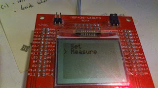
After few small modifications and settings, the tachometer was installed on the home-made experiment motor.
The sensor is placed on the top of the rotor using a wooden pole, so to be perfectly aligned with the rotor's magnets.

If somebody is interested to have the source code just contact me
Requirements
The kind of motor built for the experiment is slow by definition, so the RPM meter (also called tachometer - http://en.wikipedia.org/wiki/Tachometer) must be capable to measure and display low revolutions per minute.
The other goal is to build the tool easily and in short time, possibly spending the less possible.
The other goal is to build the tool easily and in short time, possibly spending the less possible.
Acquiring Methods
The first problem to solve is how to acquire the rotor revolutions, i.e. how to translate a movement in an electric signal.
Usually there are two methods :
- magnetic
- optical
Magnetic
Since the rotor has already magnets glued on it, it is relatively easy to add a magnetic sensor capable to generate a pulse every time a magnet pass close to it.The sensor can be a reed switch or, typically, a Hall sensor. The Hall sensor is better than the Reed switch because is not mechanical, so is not generating false signals and is faster.
If an Hall sensor is used, it must be unipolar.
There are two kind of Hall sensors, unipolar and bypolar.
The bypolar requires to "see" a change pole. i.e. a change from South pole to North pole and viceversa. Every change, triggers the change of the electric signal.
The unipolar sensor change the state of the electric signal every time a South pole is close to the sensor.
Here a graph to show the two kind of Hall sensors :

When the South pole is close to the sensor, the output signal goes down. Only when the North pole is close to the sensor, the output signal goes back high.
The lower part of the graph shows a unipolar Hall sensor.
When the South pole is close to the sensor, the output goes down and it goes up as soon as the South pole is going away from the sensor.
Optical
The other common way to acquire the revolution, is optical.Typically on the rotor is glued a reflective surface in a spot. A Infrared ray is sent toward the rotor and a circuit can detect the reflection of the infrared ray when bounced back from the reflective surface.
As alternative is possible to attach a disc with holes to the rotor and have a light beam (or infrared beam) interrupted by such disc.
A third optical alternative is to attach to the rotor a "black and white" pattern and illuminate it with a stroboscopic light.
Changing the frequency of the light until the pattern is "stable" (or visible as it would be stopped) will give the RPM.
Measurement
We have a series of pulses generated by the sensor.
Let assume we are using the magnetic acquiring method, with a unipolar Hall sensor.
Depending how many magnets we have on the rotor we can have "n" pulses for every revolution.
i.e if we have two magnets on the rotor, we'll have two pulse every revolution. 4 magnets will generate 4 pulses and so on.
The "intuitive algorithm is quite easy. We need to count the number of pulses in a minute, then divide the number for the number of magnets and the result will be our RPM.
Unfortunately this method has a drawback. We need to wait a minute before to see the result and after that, we need to wait another minute before to see changes.
So we need to reduce the acquiring time and then estimate the RPM from the minor number of readings.
For example we can count the pulses for 1 second, then divide the number of pulses by the number of magnets. The number will represent the number of revolution for second. If we multiply that number for 60, will have the number of revolution per minute (1 minute = 60 seconds).
This can work well assuming the motor rotates at a constant rate and that rate is not too slow.
For very slow rotations, it is necessary to increase the counting time, maybe to two or three seconds (and then multiply accordingly)
The problem with that is the "visualization" of the measurement. More time to count the pulses means more time between the visualization of the result.
Building
It is possible to build the tachometer in many different ways.
Of course today is more simple to use a microcontroller rather than use more "traditional" ways, like using counters, decoders and LED display.
Any microntroller family is more than suitable for this application, especially because the measurements to do are not critical.
A microcontroller is also better than "traditional logic" because it require less components and only changing the software is possible to change the type of measurement.
Mostly because is something I already have around, the idea is to use the Texas Instrument MSP430 family of microcontroller, specifically a board with already the MSP430F169 and a Philips LCD display.
The software will be build using the GNU Msp430 Gcc compiler.
Note ! It is possible to use the software on different boards with few modifications.
For example the MSP430 Launchpad board is more than enough for this project.
Only two reasons did let me decide for the Olimex board :
For example the MSP430 Launchpad board is more than enough for this project.
Only two reasons did let me decide for the Olimex board :
- I already had this board around picking up dust
- This board has already a joystick and LCD display on it
Tools
In order to develop the RPM meter (or tachometer) some tools are necessary.
The software will be build under a Linux machine, using Code::Blocks as editor/IDE.
The compiler used is the open source version of the GNU Gcc for the MSP430 .
The debug system is based on the msp430-gdbserver.
An oscilloscope will be used to check the input signal from the Hall sensor.
The PC used to develop the code must have a traditional parallel port since the only GDB tool is parallel.
For the schematics, the FidoCad and Eagle programs will be used.
FidoCad allows to draw very simple schematics, Eagle is more sophisticate and can be used to produce a PCB (not necessary for this particular project though)
Hardware
As introduced before, the main hardware is the Olimex board based on the MSP430F169.
What is needed is the Hall sensor. I choose a Honeywell SS400 series Unipolar Hall sensor (SS441A ).
The sensor will be connected to an I/O pins of the board, one capable to read the output signal from the sensor.
Since the board has plenty of available I/O Pins is not a problem.
Specifically will be used the Pin1.1 to read the signal from the Hall Sensor.

The sensor needs to be powered with a Vcc starting from 3.8 V. The Olimex board is operating at 3.3.V so an external regulator is needed and a 5V one is used. Because the MSP430F169 I/O pin are NOT 5V tolerant a resistor limiting the current is needed to avoid damage to the microcontroller.
The capacitors are the standard ones for the 78L05 regulators.
Here is possible to find the schematic of the Olimex board.

Software
First draft
The software is a first simple draft to prove the concept and verify the hardware.
It is based on the original demo code coming with the board, modified for the specific needs.
The Hall sensor signal will be connected to an interrupt capable I/O in order to don't miss any "firing" of the signal.
One or more timers will be used for the time counting. The visualization will be placed in the main loop.
The algorithm is quite simple and based on two interrupts.
One interrupt is related to the I/O pin connected to the Hall sensor. Normally the signal is pulled up, so the interrupt is set to fire on the descending slope of the signal.
The interrupt function increment a counter every time the signal goes down.
The other interrupt is a timer.
A generic timer "fires" every "n" seconds (default is 1).
When the timer fires, the the counter is copied in a variable and the counter is set to zero.
A flag is set to one indicating the need to display the content.
In the main loop, the visualization loop check the variable updated by the visualization timer to show the result.
I/O Settings
Some I/O are "forced" by the nature of the board.
Here the main ones used other than the ones pre-wired on the board :
P1.1 Hall sensor input
Pulled up, the pin goes to zero when a South Pole magnetic field is close to the sensor
P2.1 Status LED - toggle at every Hal sensor signal
The LED is toggled at every sensor magnetic event
P2.2 Status clock
The pin is toggled at every timer firing. If the timer is set for 1 second, the signal will have 2 second period.
2 seconds timer will generate a 4 seconds period on the pin and so on.
P2.3 Debug pin
Generic debug pin
Clock settings
The Olimex MSP430F169 LCD board has two crystal sources.
A 32Khz crystal and a 8 Mhz crystal.
For this application one of them should be OK since the low time involved.
The minimum period needed is about 1 second, so also the slower but precise 32Khz source should be OK as clock.
In order to minimize the timer interrupts generated, the 32 Khz crystal is used in order to generate a 1 second timer used for the measurement, the rest of the board continue to use the DCO as main source of the clock.
To set the 32Khz crystal :
DOCTL = 0x60
modulation off, DCOx and RSELx ~800kHz
BCSCTL1 = 0xB7
XT2OFF = 1 - XTS = 0 - DIVAx = 3 - RSELx = 7
BCSCTL2 = 0x00
SELMx = 0 - DIVMx = 0 - SELS = 0 - DIVSx = 0 = DCOR = 0
BCSCTL3 = 0x0C
XT2Sx = 0 - LFXT1Sx = 0 - XCAPx = 12.5pF - XT2Of = 0 - LFXT1OF = 0
With this setting the ACLK is of 4096 Hz, the MCLCK/SMCLK of ~800kHz
Note : using the 32Khz for the main clock (MCLK) the display is not working properly.
Timer setting
A generic timer is handling some sub-timers used to count the Hall sensor pulse and display the value.
The timer_A 0 will be used in the up mode.
The clock source for the timer will be ACLK, i.e. 4096 Hz.
The Timer_A will be set with a /8 so that the value 512 placed in the TACCR0 will generate an interrupt every 1 second.
TACTL = TASSEL_1 + ID_3 + MC_1; /* Uses ACLK, divide by 8, count in up mode */
TACCTL0 = CCIE; /* Use TACCR0 to generate interrupt */
TACCR0 = TMRVALUE; /* 1s */
Menu
When the code starts, a menu appears.Two choices are available :
- Set
- Measure
The Set allows to set up some parameters, like the number of seconds for the counter/display value or the number of magnets
The Measure starts the measurement.


Update
After few small modifications and settings, the tachometer was installed on the home-made experiment motor.
The sensor is placed on the top of the rotor using a wooden pole, so to be perfectly aligned with the rotor's magnets.
If somebody is interested to have the source code just contact me
Sunday, October 16, 2011
Olimex MSP430F169 LCD board
One of these is the MSP430-169LCD. This article contains some notes about the board, tests operations and tips/tricks. |
This development kit is very interesting.
FEATURES:
- MCU: MSP430F169 with 60K Bytes Program Flash, 256 Bytes data Flash,2K Bytes RAM
- NOKIA 3310 LCD 84x48 pixels black & white
- Joystick with 4 directions and push button function
- SD/MMC card connector
- two LEDs: status and power
- RESET switch
- JTAG connector
- 32 768 Hz oscillator crystal
- 8Mhz crystall oscillator
- power supply voltage regulators and filtering capacitor
- extension headers for all uC pins
- PCB: FR-4, 1.5 mm (0,062"), soldermask, white silkscreen component print
- Dimensions: 67x66 mm (2.65x2.6")
Linux development environment
First of all, I installed the mspgcc development system.
Since I use Ubuntu I installed it (another article will describe that ), then I installed the program msp430-gdbproxy and the libraries from the Soft-switch.org website.
This is very critical.
The msp430-gdbproxy must be copied in the directory where is installed the mspgcc environment (usually /usr/msp430/bin, but in my case /opt/msp430-gcc-4.4.3/bin) and the two libraries libHIL.so and libMSP430.so, must be copied in the directory /usr/lib.
It is vital to copy the program and libraries from the same site, i.e. compiled for the same version.
The mspgcc installation process already copy the libHIL.so and libMSP430.so but very likely these libraries are NOT in sync with the msp430-gdbproxy program.
JTAG test
Then I started to see if the Olimex board was working.
I connected a 9V battery to the board (Vin and GND) and the board become alive.
Then, removing the external power, I connected the board to the JTAG connector, already hooked to the parallel port of the PC.
The board come alive, since the JTAG connector, thru the jumper P-IN (inserted by default), bring the power.
At this point, following the instructions found on the Develissimo website and from this article on the MSP430 development environment , I started the msp430-gdbproxy in a terminal.
The first time I had strange error, so I reset the board and something started finally to work.
However using the suggested command :
#msp430-gdbproxy --port=2000 msp430
I obtained this error :
debug: MSP430_Configure()
error: msp430-gdbproxy: unable to open debugger connection. Will restart
I spent quite some time tracking this error but the only thing I realized, was that the error was somehow related to the TCP port used or about some conflict with other services or the Linux configuration.
Then I started to read the mspgcc documentation and I found some notes about the msp430-gdbproxy .
In the notes it was suggested to try the command:
#msp430-gdbproxy --debug msp430
and it worked !
Only I noted that the default port was not 2000 but 2001 !
So I modified the original command using the new port :
#msp430-gdbproxy --port=2001 msp430
and ... voila' !!!
I was able to connect the Olimex board with the JTAG.
So to recap, in order to open a debug session with the card :
- connect the Olimex board to the Jtag (parallel version)
- open a terminal and start the gdb proxy :
msp430-gdbproxy --port=2001 msp430
Note ! If is not working is possible to use sudo, but in this case the absolute path of the msp430-gdbproxy must be issued.
For example in my case : sudo /opt/msp430-gcc-4.4.3/bin/msp430-gdbproxy msp430 - open another terminal, or a tab in the already opened, and start the gdb :
msp430-gdb name_program_to_load.elf
Here some common operations :
- connect to the board (first thing to do)
target remote localhost:2001 - erase the flash memory (needed to do every time before to load the new code)
monitor erase - load a program in the flash
load name_program_to_load.elf (or .a43)
The first test is to convert the IAR demo code available for this board, for the mspgcc.
Following the conversion rules , it is possible to compile with mspgcc the code.
To simplify the process I created a makefile. Looking at what files the IAR used to create the code, I created a simple makefile :
CC=msp430-gcc
CFLAGS=-O0 -Wall -g -mmcu=msp430x169
OBJS=main.o mmc.o system.o lcd_new.o
all: $(OBJS)
$(CC) $(CFLAGS) -o test.elf $(OBJS)
%.o: %.c
$(CC) $(CFLAGS) -c lt;
clean:
rm -fr main.elf $(OBJS)
To compile the code, simply open a terminal, go in the directory where there is the makefile and the source code and then :
- $make clean
to clean up the objects - $make
to compile
The result is a file called test.elf that can be load directly using the procedure described above.
The code is running smoothly.
Joystick
Here some notes about the joystick on the board.
The joystick is seen as 5 different switches.
The higher 4 bit of the Port1 (set in I/O - input direction - MSB) are used to carry the state of the 4 direction switches and 1 bit of the Port 2 (set in I/o - input direction) is used to carry the state of the pushbutton.
Here a table :
| Signal | Name | Description |
| P1.4 | B1 | Right |
| P1.5 | B2 | Down |
| P1.6 | B3 | Up |
| P1.7 | B4 | Left |
| P2.0 | B5 | Pushbutton |
The signals are pulled up, so when the switch is NOT pushed the reading will be high (1).
Here a Schematic to indicate the combinations of signals (remember, a 0 means the switch is pushed).

The inner circles indicates the name of the connection on the schematic.
Pushing the joystick on the left for example, will generate the combination of 0x7x (0111xxxx), i.e. masking the MSB will have 0x70 (01110000).
Pushing the joystick Up and Right will generate the masked combination of 0xA0 (10100000).
Here some other link to related resources and examples.
Subscribe to:
Posts (Atom)