For one of the projects I want/need to do, it was necessary to measure an airflow.
Here how I built a small sensor for that.
The simplest way to do so is to modify a computer fan.
I choose a small brush-less fan (for CPU), with ball bearings.
Circuit
Probably the simplest and safest way to detect the rotation of the blade, is to use an Hall Effect sensor.
The sensor is placed inside the fan case, instead of the original motor circuit.
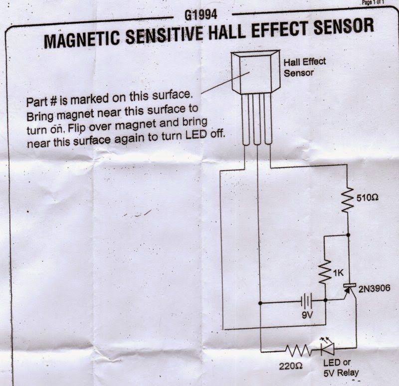
Below the bipolar Hall Effect sensor I used. No really need to have a bi-polar Hall Effect, actually a single pole Hall Effect it would work better, but this is what I had around at the time.
Hardware preparation
The first step was to split the rotor from the main case.
Usually there is a small groove that keep the rotor in place.
On the rotor, in this type of fan, there is the permanent magnet.
It need to be removed.
The motor is usually soldered to a PCB, just stuck in the plastic case.
With some force is possible to disconnect it.
3 wires, as the original configuration of the fan, are required for the Hall sensor.
Vdd, GND and the output.
Here some pictures of the conversion, starting from the original CPU fan I used (below)
The first thing was to take it apart, removing the motor and electronic.
Then I glued an Hall Effect sensor close to the shaft, on the base.
On the propeller, I attached two earth rare magnets (very small and very powerful), on the opposite sides.
I left the metal rim inside to facilitate the magnet attach (I also glued them) and to give a little bit weight to the propeller.
The magnets are attached with the poles in the opposite direction, because the Hall Effect sensor I used is a bipolar one, i.e. it needs to "see" a North/South pole change in order to go on, and a South/North pole change to go off.
Here the anemometer completed, attached to a simple circuit to test the Hall Effect sensor.
In the last picture, it is possible to see also the 1 wire temperature sensor (DS18S20) connected to the cable.
It is the sensor needed to detect the temperature of the air flow.
A simple first prototype , using an MSP430-2013, it was built to develop and test the firmware to read the anemometer and the temperature sensor.