| Time ago a friend of mine, Molly, asked me to help her to prepare some electronic effects for a costume : Boba Fett from Star Wars. At the time I prepared some articles to document the work. Here the material I prepared, edited for the blog. This is the first article, others will follow. Basically there was two areas of the costume where I helped :
Rangefinder The rangefinder is, in the character fiction, a device capable to identify and point a target. Physically is a funny shaped box, with some flashing lights and a screen, mounted on the top of a rod/pole, on the side to the helmet. When not in use it rest vertically. When in use it is lift down in front to the visor. There are two flashing lights in front and a "screen" in the back of the rangefinder, just in front of the visor. The lights are turned on when the rangefinder is lifted down. Lights The rangefinder has three lights, supposedly going on when in the horizontal position. Two flashing lights in front and one green or white light inside, in order to simulate the light from a monitor screen . It is possible to design different circuits capable to drive the lights.
Simple The circuit is quite simple and "classic" and can even be minimized using special components, like this : The circuit is extremely simple. A 3V coin battery to power supply 3 LEDs and a tilt switch turn on the LEDs when the rangefinder is horizontal. Two of them will be "flashing LED", i.e. LED with already included an oscillator, like this one found on AllElectronics. Pros :
Classic Alternatively, is possible to build an astable oscillator, using a couple of transistor, so to have the LEDs flashing alternatively and not in "simil sync" as the previous circuit. Adopting an astable oscillator is little bit more complicated and it require a PCB (a piece of sperimental board is ok). Something like that : The circuit seems more complicated but is really not. Is a "classic" astable multivibrator based on two transistor NPN who drive two normal LEDs (D1 and D3). D2 is a green or light LED. Pros :
Flexible The third way to drive the LEDs is, for my taste, the better. Using a microcontroller, we can achieve the maximum about flexibility and an easy to program and change effects. The hardware is very very simple, based on a MSP430F2012 microcontroller. Simply we can connect the three LEDs to the micro I/O ports using the micro PCB. After that is only matter to write a simple firmware capable to drive the LEDs. It is quite easy to set up any pattern and also include some special effects on the one that simulate the screen. The 3 LEDs will be connected to 3 I/O pin, programmed in output mode. Another pin will be used to connect the tilt switch. The tilt switch is not used to power supply the micro, because is not capable to give a neat on/off signal. In this way the micro will read the tilt switch, acting also as filter. When the tilt switch will indicate a off position, the micro will be placed in low power mode. Pros :
| |
| Movement The rangefinder is attached to the helmet. Since the goal is to have it moving automatically, from the vertical position to the horizontal one, a motor and gears will be needed. The main challenge for the mechanic part, is the dimension and the torque needed to move the rangefinder. Because the dimension, some limits will exist :
Usually is in vertical position but can be lowered in the horizontal position. The idea is to make the Rangefinder move from vertical to horizontal, and back, automatically. The electronic to control the movement, will be based on a MSP430F2012 Texas Instrument microcontroller plus other components. Like the lights, there are different possible choices. The first is to use a normal DC motor, coupled with some gears. The second, the one we adopted, uses a servocontroller.
DC Motor A RF receiver will provide the input for the microcontroller (a Texas Instrument MSP430F2012), that will drive a H bridge capable to power the DC motor in both directions. The DC motor, geared, will in the end move the rangefinder up or down. Servo The alternative to drive directly the motor and play with a gearbox, is to use a servo. A "servo" is a "servomotor". Basically a "ready to use" DC motor, with a gearbox and an electronic circuit capable to drive it. The advantage is that the motor is already handled by an electronics, easily controllable by a microcontroller. There are many different models of "servo". They are used in the models (planes/boats/cars) and usually have a strong torque available. Here a schematic block that illustrate what we have to do : |

Technical blog to share ideas about Home Automation and other things.
Wednesday, March 30, 2011
Boba Fett project

Saturday, March 26, 2011
Apache log messages on the Infoglobe
The RS232 version of the Infoglobe Interface is capable to receive RS232 messages from a system, not only from a terminal emulator.
So, in order to test this capability, here a note about how to create a "custom" log message from the server Apache and have it sent to the interface.
In order to send a log message to the interface, we have to create a specific log capable to "fit" the Infoglobe message length.
The infoglobe is capable to display a maximum of 36 characters and also some characters are not available.
Because of that we have to create a log with the minimum information possible.
Log generation
Fortunately is quite simple to create custom log files with Apache.
It's enough to open the http server configuration file (in my case, on CentOS /etc/httpd/conf/httpd.conf) and create a log generation customized for our needs.
In this configuration file, just search for the word LogFormat.
Usually there are some LogFormat lines in the file.
We have to create our own. Here the line I prepared :
LogFormat "^%{%D,%T}t %h " infoglobe
Basically I want to display only the date/time of the access and the IP.
%t display the time, but since the default format is quite huge, I used the strtime format to create a shorter date/time string.
You can find more information about the log capabilities of Apache in the Apache documentation.
Then in the part of the configuration file where the server is defined (in my case a Virtual server) just create a log entry using the LogFormat you prepared.
In my case :
CustomLog logs/apkh_infoglobe infoglobe
Now every time someone access the server, a file called apkh_infoglobe will contains date/time and IP of the access, something like :
^08/12/07,15:00:04 68.46.241.153
Note the first character.
When the Infoglobe interface receive the character '^' will display the message in rotation.
Log presentation
After restarting the server (every modification to the configuration file will require a restart of the server), every access will add a line the log file.
To send the log file, in automatic way, to the Infoglobe, is enough to use this command, assuming of course the /dev/ttyS0 (equivalent to COM1 under DOS) is connected to the Infoglobe interface :
# tail -f -n 1 log_file > /dev/ttyS0
In my example :
# tail -f -n 1 apkh_infoglobe > /dev/ttyS0
After that, every access to the server will be showed up on the Infoglobe.
That's it !
Here an extract of the log file apkh_infoglobe :
.....................
.....................
^08/15/07,00:05:47 68.46.241.153
^08/15/07,00:05:34 68.46.241.153
^08/15/07,00:05:47 68.46.241.153
^08/15/07,00:05:26 68.46.241.153
^08/15/07,00:05:52 68.46.241.153
^08/15/07,00:06:05 68.46.241.153
^08/15/07,00:06:05 68.46.241.153
^08/15/07,09:26:59 68.46.241.153
^08/15/07,09:27:03 68.46.241.153
^08/15/07,11:17:41 66.249.66.40
^08/15/07,11:17:41 66.249.66.40
^08/15/07,11:22:37 68.46.241.153
^08/15/07,11:22:43 68.46.241.153
^08/15/07,11:22:44 68.46.241.153
^08/15/07,11:22:46 68.46.241.153
^08/15/07,11:22:46 68.46.241.153
^08/15/07,11:22:46 68.46.241.153
^08/15/07,11:22:46 68.46.241.153
^08/15/07,11:22:47 68.46.241.153
^08/15/07,11:22:47 68.46.241.153
^08/15/07,11:22:47 68.46.241.153
^08/15/07,11:22:47 68.46.241.153
^08/15/07,11:22:47 68.46.241.153
^08/15/07,11:22:51 68.46.241.153
^08/15/07,11:22:56 68.46.241.153
^08/15/07,11:23:00 68.46.241.153
^08/15/07,11:23:00 68.46.241.153
^08/15/07,11:23:02 68.46.241.153
^08/15/07,15:46:05 74.6.19.79
^08/15/07,16:46:31 66.249.66.40
.....................
.....................
Important to remember that the tail command is sending always the LAST line as soon as it is generated.
Here a picture of the Infoglobe showing the temperature :

Here the Infoglobe showing an IP from the log :

So, in order to test this capability, here a note about how to create a "custom" log message from the server Apache and have it sent to the interface.
In order to send a log message to the interface, we have to create a specific log capable to "fit" the Infoglobe message length.
The infoglobe is capable to display a maximum of 36 characters and also some characters are not available.
Because of that we have to create a log with the minimum information possible.
Log generation
Fortunately is quite simple to create custom log files with Apache.
It's enough to open the http server configuration file (in my case, on CentOS /etc/httpd/conf/httpd.conf) and create a log generation customized for our needs.
In this configuration file, just search for the word LogFormat.
Usually there are some LogFormat lines in the file.
We have to create our own. Here the line I prepared :
LogFormat "^%{%D,%T}t %h " infoglobe
Basically I want to display only the date/time of the access and the IP.
%t display the time, but since the default format is quite huge, I used the strtime format to create a shorter date/time string.
You can find more information about the log capabilities of Apache in the Apache documentation.
Then in the part of the configuration file where the server is defined (in my case a Virtual server) just create a log entry using the LogFormat you prepared.
In my case :
CustomLog logs/apkh_infoglobe infoglobe
Now every time someone access the server, a file called apkh_infoglobe will contains date/time and IP of the access, something like :
^08/12/07,15:00:04 68.46.241.153
Note the first character.
When the Infoglobe interface receive the character '^' will display the message in rotation.
Log presentation
After restarting the server (every modification to the configuration file will require a restart of the server), every access will add a line the log file.
To send the log file, in automatic way, to the Infoglobe, is enough to use this command, assuming of course the /dev/ttyS0 (equivalent to COM1 under DOS) is connected to the Infoglobe interface :
# tail -f -n 1 log_file > /dev/ttyS0
In my example :
# tail -f -n 1 apkh_infoglobe > /dev/ttyS0
After that, every access to the server will be showed up on the Infoglobe.
That's it !
Here an extract of the log file apkh_infoglobe :
.....................
.....................
^08/15/07,00:05:47 68.46.241.153
^08/15/07,00:05:34 68.46.241.153
^08/15/07,00:05:47 68.46.241.153
^08/15/07,00:05:26 68.46.241.153
^08/15/07,00:05:52 68.46.241.153
^08/15/07,00:06:05 68.46.241.153
^08/15/07,00:06:05 68.46.241.153
^08/15/07,09:26:59 68.46.241.153
^08/15/07,09:27:03 68.46.241.153
^08/15/07,11:17:41 66.249.66.40
^08/15/07,11:17:41 66.249.66.40
^08/15/07,11:22:37 68.46.241.153
^08/15/07,11:22:43 68.46.241.153
^08/15/07,11:22:44 68.46.241.153
^08/15/07,11:22:46 68.46.241.153
^08/15/07,11:22:46 68.46.241.153
^08/15/07,11:22:46 68.46.241.153
^08/15/07,11:22:46 68.46.241.153
^08/15/07,11:22:47 68.46.241.153
^08/15/07,11:22:47 68.46.241.153
^08/15/07,11:22:47 68.46.241.153
^08/15/07,11:22:47 68.46.241.153
^08/15/07,11:22:47 68.46.241.153
^08/15/07,11:22:51 68.46.241.153
^08/15/07,11:22:56 68.46.241.153
^08/15/07,11:23:00 68.46.241.153
^08/15/07,11:23:00 68.46.241.153
^08/15/07,11:23:02 68.46.241.153
^08/15/07,15:46:05 74.6.19.79
^08/15/07,16:46:31 66.249.66.40
.....................
.....................
Important to remember that the tail command is sending always the LAST line as soon as it is generated.
Here a picture of the Infoglobe showing the temperature :
Here the Infoglobe showing an IP from the log :
Wednesday, March 23, 2011
CY7C68013A USB Logic Analyzer
I received to test a little board based on the Cypress CY7C68013A.
Here some notes about this experience.

The CY7C68013A USB Logic Analyzer is a small board made by a Chinese company (Lcsoft) sold on Ebay from a China reseller as a Logic Analyzer tool.
It's a small board based on a Cypress CY7C68013A micro-controller (an 8051 clone).
First impressions
The board arrived in a small padded envelop, without any cable, documentation and software.
Quite useless due the totally lack of information.
Looking over the net didn't return too much information, there are very few seller of this product.
On some Ebay auctions for this board, there were present some links to the schematics and software, however these links seems not working.

Being only in Chinese is not really helpful to understand what is going on, also if it appears a "button" is available, but it is disabled (gray one).
Also the download material available on these links, is information-less.
Are basically 3 rar files named 0000.rar, 1111.rar and 2222.rar, not really self explaining.
I had to contact the vendor of the board, and he initially answered back giving me the link to the same URL I discovered not working.
After another round of contacts, the vendor sent me the files via email.
Fortunately, at least under Linux, almost all in the end was accessible.
Without entering too much in detail here some contents, for what I can say (no documentation is present) :
To better organize the received material, I created a new tree , changing some names to better identify the pieces :
Doing some tests using the program Logic under Windows (1.0.21), it seems that the 8 inputs used are located in the port B, where PB0 is the Input 1, PB1 the input 2 and so on.
The pins not connected to a probe input, reports an high value (+5V), i.e. seems the inputs are pulled up.
Also from the tests it seems the board can support max 8Mhz as input frequency.
The possible selection of the program Logic (12 Mhz, 16 Mhz and 24 Mhz) are not working.
The program automatically reduce them to lower values if selected.
From some tests, it appears that all the selections of frequency are working, however the combination of the frequency and the number of samples can cause the program to "scale down" the frequency selection.
When the jumper close to the Eeprom is removed, the board is not seen anymore as Logic Analyzer but as Cypress development board.
Probably in the Eeprom are stored the codes and/or firmware for the Logic analyzer.
Some sellers of the board (and similar one) sells a cable that can be connected to the board, but I didn't like it for the price, the endless waiting time (from Honk Kong) and the appearance.
So I decided to buy the cable used by the Logic original hardware and build a simple adapter board to connect it.
I bought the cable from Sparkfun (TOL-09225).
Here a couple of pictures of the adapter board to connect the cable to the logic analyzer.
The Logic Analyzer
There is also another Logic analyzer code, the Logic, from Saleae , that exist also for Linux .
So in order to see if the board is actually working, here are some required steps :
The program requires some .Net libraries, I suspect the ones received with the rest of the code.
However the installation checks and installs them from the Microsoft website directly.
The .Net framework installation takes some time, so it is mandatory to have patience.
After restarted the computer and completed the installation, it is possible to launch Logic, after connecting the board.
The board is recognized and the program is able to read the signals.
Status : working
There is no need to install the code, however in the Driver directory there is an udev entry and a small script capable to copy the udev rule under /etc/udev.
So far the board is recognized (plug in) but on I have a not identified "access" problem.
lsusb recognize the board as "Lakeview Research"
Bus 001 Device 021: ID 0925:3881 Lakeview Research
Device Descriptor:
bLength 18
bDescriptorType 1
bcdUSB 2.00
bDeviceClass 255 Vendor Specific Class
bDeviceSubClass 255 Vendor Specific Subclass
bDeviceProtocol 255 Vendor Specific Protocol
bMaxPacketSize0 64
idVendor 0x0925 Lakeview Research
idProduct 0x3881
bcdDevice 0.00
iManufacturer 1
iProduct 2
iSerial 0
bNumConfigurations 1
Configuration Descriptor:
bLength 9
bDescriptorType 2
wTotalLength 46
bNumInterfaces 1
bConfigurationValue 1
iConfiguration 0
bmAttributes 0x80
(Bus Powered)
MaxPower 100mA
Interface Descriptor:
bLength 9
bDescriptorType 4
bInterfaceNumber 0
bAlternateSetting 0
bNumEndpoints 4
bInterfaceClass 255 Vendor Specific Class
bInterfaceSubClass 255 Vendor Specific Subclass
bInterfaceProtocol 255 Vendor Specific Protocol
iInterface 0
Endpoint Descriptor:
bLength 7
bDescriptorType 5
bEndpointAddress 0x01 EP 1 OUT
bmAttributes 2
Transfer Type Bulk
Synch Type None
Usage Type Data
wMaxPacketSize 0x0200 1x 512 bytes
bInterval 0
Endpoint Descriptor:
bLength 7
bDescriptorType 5
bEndpointAddress 0x81 EP 1 IN
bmAttributes 2
Transfer Type Bulk
Synch Type None
Usage Type Data
wMaxPacketSize 0x0200 1x 512 bytes
bInterval 0
Endpoint Descriptor:
bLength 7
bDescriptorType 5
bEndpointAddress 0x82 EP 2 IN
bmAttributes 2
Transfer Type Bulk
Synch Type None
Usage Type Data
wMaxPacketSize 0x0200 1x 512 bytes
bInterval 0
Endpoint Descriptor:
bLength 7
bDescriptorType 5
bEndpointAddress 0x06 EP 6 OUT
bmAttributes 2
Transfer Type Bulk
Synch Type None
Usage Type Data
wMaxPacketSize 0x0200 1x 512 bytes
bInterval 0
can't get device qualifier: Connection timed out
can't get debug descriptor: Connection timed out
cannot read device status, Connection timed out (110)
However some info I found suggest that the board should give more information.
Status : NOT working
Logic 1.1.9 (Ubuntu)
The Ubuntu (32 bit) version tested is the 1.1.9.
There is no need to install the code, however in the Driver directory there is an udev entry and a small script capable to copy the udev rule under /etc/udev.
So far the board is recognized (plug in) but on I have a not identified "access" problem.
lsusb recognize the board as "Lakeview Research".
The installation was successful, however like the Ubuntu version, is not full recognizing the board, aborting immediately after the board is connected to the USB.
A collateral effect I had so far, is that the board is not working anymore also with the 1.0.21 version of Logic until the new Logic program 1.1.4 is dis-installed and the computer restarted.
Status : NOT working (not yet tested with the update)
The version, only for Windows, is called 1.0.33 (present also in this website) and is working.
Status : working
USBee Suite 1.5.7 (Windows)
The other included Logic analyzer application is the USBee Suite, version 1.5.7.
The installation went well, no errors (on my Win XP machine) but the code it crash as soon as it starts, after the splashscreen.
Doesn't matter to have the board connected or not to the computer.
Status : NOT working
The lack of information make really complicate to try to study the reason of the failure with newer version of the Logic or Linux version, but I think has to do with a lack of information to the USB udev.
Also in order to use the board is necessary to :
For the price is sure an interesting object, but the lack of information and the reduced capabilities if compared with "official" products can reduce the usefulness of the product.
If having reduced capabilities, like be forced to use Windows instead of Linux and the limit in the frequency input, having to build the case for the board, play with the received material and lack of information (that this article tries to fix), then it can make sense to spend the money.
Otherwise I think the full price of the "originals" like the Saleae Logic are more than well justified.
Here some notes about this experience.

The CY7C68013A USB Logic Analyzer is a small board made by a Chinese company (Lcsoft) sold on Ebay from a China reseller as a Logic Analyzer tool.
It's a small board based on a Cypress CY7C68013A micro-controller (an 8051 clone).
First impressions
The board arrived in a small padded envelop, without any cable, documentation and software.Quite useless due the totally lack of information.
Looking over the net didn't return too much information, there are very few seller of this product.
On some Ebay auctions for this board, there were present some links to the schematics and software, however these links seems not working.

Being only in Chinese is not really helpful to understand what is going on, also if it appears a "button" is available, but it is disabled (gray one).
Also the download material available on these links, is information-less.
Are basically 3 rar files named 0000.rar, 1111.rar and 2222.rar, not really self explaining.
I had to contact the vendor of the board, and he initially answered back giving me the link to the same URL I discovered not working.
After another round of contacts, the vendor sent me the files via email.
The software
As I mentioned earlier, the software associated to this board, is coming in three "anonymous" RAR files :- 0000.rar
- 1111.rar
- 2222.rar
0000.rar
This file contains other rar files, some of them named in Chinese and thus with wrong/illegal names in English.Fortunately, at least under Linux, almost all in the end was accessible.
Without entering too much in detail here some contents, for what I can say (no documentation is present) :
- -rw-r--r-- 1 1118001 2007-01-02 00:13 56pin.rar
Source code for the board firmware.
There are different directories and is not clear if all the code present is part of what is written on the chip or if there are testing code, experiments, ecc.
There is NO documentation, nor information, nor about the necessary tools to compile the code and how to load it in the chip. - -rw-r--r-- 1 1701745 2007-01-02 00:13 Logic Software 1.0.21.rar
Windows version Logic analyzer program in binary, no documentation.
It is from the USBee Suite . - -rw-r--r-- 1 229606 2007-01-02 00:13 Schematic.rar
Schematic and BOM of the board
1111.rar
This file contains a single zip file, that in the end contains a MSIA loader (Microsoft stuff)- -rw-r--r-- 1 11416917 2009-02-18 02:13 axsw.zip
2222.rar
Also this file contains a single zip file that contains some USB drivers for Windows.- -rw-r--r-- 1 8372169 2010-05-05 11:21 usbeesuitesw.zip
To better organize the received material, I created a new tree , changing some names to better identify the pieces :
- drwxr-xr-x 7 4096 2010-11-01 16:23 Firmware
This directory contains the firmware supposedly on board - drwxr-xr-x 2 4096 2011-03-18 12:29 LogicAnalyzer
It seems a logic analyzer code. Not sure if is equivalent to the UsbeeSuite or it is part - drwxr-xr-x 2 4096 2011-03-18 07:05 Msia
Microsoft libraries - drwxr-xr-x 2 4096 2007-01-02 03:37 Schematics
Schematics of the board - drwxr-xr-x 2 4096 2011-03-18 07:05 UsbeeSuite
Usbee Suite 1.5.7
The hardware
The schematic present in the received files, it just illustrates the board "as is", without any indication about how to use it for the Logic Analyzer function.Doing some tests using the program Logic under Windows (1.0.21), it seems that the 8 inputs used are located in the port B, where PB0 is the Input 1, PB1 the input 2 and so on.
The pins not connected to a probe input, reports an high value (+5V), i.e. seems the inputs are pulled up.
From some tests, it appears that all the selections of frequency are working, however the combination of the frequency and the number of samples can cause the program to "scale down" the frequency selection.
When the jumper close to the Eeprom is removed, the board is not seen anymore as Logic Analyzer but as Cypress development board.
Probably in the Eeprom are stored the codes and/or firmware for the Logic analyzer.
The cable
The analyzer arrived without any cable, so I looked around to see what was the best approach.Some sellers of the board (and similar one) sells a cable that can be connected to the board, but I didn't like it for the price, the endless waiting time (from Honk Kong) and the appearance.
So I decided to buy the cable used by the Logic original hardware and build a simple adapter board to connect it.
I bought the cable from Sparkfun (TOL-09225).
Here a couple of pictures of the adapter board to connect the cable to the logic analyzer.
The Logic Analyzer


Exploring the received files, I didn't find a single piece of documentation about how to set up both software and hardware, the logic analyzer functionality.
From some comments and the nature of the code, I think that the package (hardware and software) is a clone (hack ?) of the USBee LX series of USB instruments .There is also another Logic analyzer code, the Logic, from Saleae , that exist also for Linux .
So in order to see if the board is actually working, here are some required steps :
- try to install on a Windows machine the included software :
- USBee Logic Analyzer Suite
- Microsoft Net extensions
- Saleae Logic analyzer (Version 1.0.21)
- check the installed software in order to find hardware hook up info
- connect the hardware to the PC and see if is working and discover how to use the board I/O
- try to do the same with the Linux version
Install code
Logic 1.0.21 (Windows)
One for the Windows code in the received files, is from the Saleae, Logic, version 1.0.21.The program requires some .Net libraries, I suspect the ones received with the rest of the code.
However the installation checks and installs them from the Microsoft website directly.
The .Net framework installation takes some time, so it is mandatory to have patience.
After restarted the computer and completed the installation, it is possible to launch Logic, after connecting the board.
The board is recognized and the program is able to read the signals.
Status : working
Logic 1.1.4 (Ubuntu)
The Ubuntu (32 bit) version tested is the 1.1.4.There is no need to install the code, however in the Driver directory there is an udev entry and a small script capable to copy the udev rule under /etc/udev.
So far the board is recognized (plug in) but on I have a not identified "access" problem.
lsusb recognize the board as "Lakeview Research"
Bus 001 Device 021: ID 0925:3881 Lakeview Research
Device Descriptor:
bLength 18
bDescriptorType 1
bcdUSB 2.00
bDeviceClass 255 Vendor Specific Class
bDeviceSubClass 255 Vendor Specific Subclass
bDeviceProtocol 255 Vendor Specific Protocol
bMaxPacketSize0 64
idVendor 0x0925 Lakeview Research
idProduct 0x3881
bcdDevice 0.00
iManufacturer 1
iProduct 2
iSerial 0
bNumConfigurations 1
Configuration Descriptor:
bLength 9
bDescriptorType 2
wTotalLength 46
bNumInterfaces 1
bConfigurationValue 1
iConfiguration 0
bmAttributes 0x80
(Bus Powered)
MaxPower 100mA
Interface Descriptor:
bLength 9
bDescriptorType 4
bInterfaceNumber 0
bAlternateSetting 0
bNumEndpoints 4
bInterfaceClass 255 Vendor Specific Class
bInterfaceSubClass 255 Vendor Specific Subclass
bInterfaceProtocol 255 Vendor Specific Protocol
iInterface 0
Endpoint Descriptor:
bLength 7
bDescriptorType 5
bEndpointAddress 0x01 EP 1 OUT
bmAttributes 2
Transfer Type Bulk
Synch Type None
Usage Type Data
wMaxPacketSize 0x0200 1x 512 bytes
bInterval 0
Endpoint Descriptor:
bLength 7
bDescriptorType 5
bEndpointAddress 0x81 EP 1 IN
bmAttributes 2
Transfer Type Bulk
Synch Type None
Usage Type Data
wMaxPacketSize 0x0200 1x 512 bytes
bInterval 0
Endpoint Descriptor:
bLength 7
bDescriptorType 5
bEndpointAddress 0x82 EP 2 IN
bmAttributes 2
Transfer Type Bulk
Synch Type None
Usage Type Data
wMaxPacketSize 0x0200 1x 512 bytes
bInterval 0
Endpoint Descriptor:
bLength 7
bDescriptorType 5
bEndpointAddress 0x06 EP 6 OUT
bmAttributes 2
Transfer Type Bulk
Synch Type None
Usage Type Data
wMaxPacketSize 0x0200 1x 512 bytes
bInterval 0
can't get device qualifier: Connection timed out
can't get debug descriptor: Connection timed out
cannot read device status, Connection timed out (110)
However some info I found suggest that the board should give more information.
Status : NOT working
Logic 1.1.9 (Ubuntu)
The Ubuntu (32 bit) version tested is the 1.1.9.
There is no need to install the code, however in the Driver directory there is an udev entry and a small script capable to copy the udev rule under /etc/udev.
So far the board is recognized (plug in) but on I have a not identified "access" problem.
lsusb recognize the board as "Lakeview Research".
Status : working
Logic 1.1.4 (Windows)
I installed also the new version of Logic, the 1.1.4, under Windows.The installation was successful, however like the Ubuntu version, is not full recognizing the board, aborting immediately after the board is connected to the USB.
A collateral effect I had so far, is that the board is not working anymore also with the 1.0.21 version of Logic until the new Logic program 1.1.4 is dis-installed and the computer restarted.
Status : NOT working (not yet tested with the update)
Logic 1.0.33 (Windows)
On the Saleae website is also present an older version of Logic, but greater than the one present in the received files from the board vendor.The version, only for Windows, is called 1.0.33 (present also in this website) and is working.
Status : working
USBee Suite 1.5.7 (Windows)
The other included Logic analyzer application is the USBee Suite, version 1.5.7.The installation went well, no errors (on my Win XP machine) but the code it crash as soon as it starts, after the splashscreen.
Doesn't matter to have the board connected or not to the computer.
Status : NOT working
Conclusion
The board is working basically only with the version of Logic 1.0.21 and Logic 1.0.33 under Windows and with limitations (max. available frequency).The lack of information make really complicate to try to study the reason of the failure with newer version of the Logic or Linux version, but I think has to do with a lack of information to the USB udev.
Also in order to use the board is necessary to :
- buy a set of 9 probes
- prepare a piggy back circuit to adapt the probe connettor
Since the board is "generic" the probe connection are not linear but the ones available on the market are. - eventually optoisolate/protect the inputs
- put the board in a case
For the price is sure an interesting object, but the lack of information and the reduced capabilities if compared with "official" products can reduce the usefulness of the product.
If having reduced capabilities, like be forced to use Windows instead of Linux and the limit in the frequency input, having to build the case for the board, play with the received material and lack of information (that this article tries to fix), then it can make sense to spend the money.
Otherwise I think the full price of the "originals" like the Saleae Logic are more than well justified.
Sunday, November 7, 2010
110V Lamp Bulb replacement
With one of the 10 Watt LED lamp kit Roberto sent, I tried to build a bulb replacement.
Here some notes and comments.
The LED power supply in the kit was round and fit perfectly the old CFL base.


The initial kit included the 10 Watt LED and a small square heat-sink with a fan.


I glued the LED to the heat-sink with a thermal compound and I attached the heat-sink to the CFL base using hot glue.
Unfortunately I don't have pictures of the first bulb replacement attempt.
It worked nicely until one day the fan broke down. Without the fan the temperature of the heat-sink was high enough to melt down the hot glue, detaching the heat-sink and the LED from the bulb base.
This time I choose to have a passive heat-sink, so I ordered one round and big enough for the 10 Watt LED.

The problem to solve was how to connect the heat-sink to the bulb base.
I decided to try the same method adopted for one of the desk lamp modifications.
Since the bulb base is around 2 inches diameter, I cut a piece of wood with that diameter.
Lee was able to drill and tap a hole in the heat-sink in order to screw it to the round piece of wood.


I did a hole in the bulb base to have the wires out and then I screwed the wood round piece to the bulb with 4 screws.
Here the lamp assembled and a detail of the attachment to the bulb base :


The only problem so far is that the bigger heat-sink prevent to use the lamp in many of my fixtures !!
Otherwise is working perfectly.


Here some notes and comments.
First attempt
I started from an old CFL lamp, removing the fluorescent tube and the electronic ballast.The LED power supply in the kit was round and fit perfectly the old CFL base.


The initial kit included the 10 Watt LED and a small square heat-sink with a fan.


I glued the LED to the heat-sink with a thermal compound and I attached the heat-sink to the CFL base using hot glue.
Unfortunately I don't have pictures of the first bulb replacement attempt.
It worked nicely until one day the fan broke down. Without the fan the temperature of the heat-sink was high enough to melt down the hot glue, detaching the heat-sink and the LED from the bulb base.
Second attempt
I had to rebuild the lamp bulb.This time I choose to have a passive heat-sink, so I ordered one round and big enough for the 10 Watt LED.

I decided to try the same method adopted for one of the desk lamp modifications.
Since the bulb base is around 2 inches diameter, I cut a piece of wood with that diameter.
Lee was able to drill and tap a hole in the heat-sink in order to screw it to the round piece of wood.


I did a hole in the bulb base to have the wires out and then I screwed the wood round piece to the bulb with 4 screws.
Here the lamp assembled and a detail of the attachment to the bulb base :


The only problem so far is that the bigger heat-sink prevent to use the lamp in many of my fixtures !!
Otherwise is working perfectly.


Friday, November 5, 2010
Flood alarm with X10

This simple project was done years ago, it can be an excellent example to show how is easy to integrate X10 in our own projects.
I needed a simple low cost flood alarm, capable to monitor some sensors and notify as soon as possible about flood conditions.
The problem
 |
| X10 Universal module |
I also needed a way to be informed in the rest of the house about a problem in the basement, where the problem happened.
So I decided to use an X10 transmitter, controlling an X10 Universal module (it has the possibility to generate a sound when triggered).
The the transmitter was modified, in order to control the pushbutton with a rele reed.
Project
Since I needed something simple, quick to build and reliable, I used the usual PIC 16F84, plus some external components (at the time I was using PICs rather then the MSP430).
Before to excite too much who is reading this article, I built the X10 interface hacking a ready-made X10 RF transmitter.
So I didn't designed nothing directly with X10.
I always try to optimize the effort and re-use as much as possible what I have around, so instead to design an X10 transmitter, with all the problems that such design imply (interface the power grid, insulation, ecc.) I choose another way also because the flood alarm is supposed to be placed in areas potentially flooded !
So I choose to use a ready-made X10 RF transmitter, drove it by a reed relay, simulating the pushbutton.
In this way I was able to obtain the requested insulation and safety and also the capability to place the alarm everywhere needed.
Here a block schematic :

Here a floor map of the basement where the flood alarm was deployed :

Before to excite too much who is reading this article, I built the X10 interface hacking a ready-made X10 RF transmitter.
So I didn't designed nothing directly with X10.
I always try to optimize the effort and re-use as much as possible what I have around, so instead to design an X10 transmitter, with all the problems that such design imply (interface the power grid, insulation, ecc.) I choose another way also because the flood alarm is supposed to be placed in areas potentially flooded !
So I choose to use a ready-made X10 RF transmitter, drove it by a reed relay, simulating the pushbutton.
In this way I was able to obtain the requested insulation and safety and also the capability to place the alarm everywhere needed.
Here a block schematic :
Here a floor map of the basement where the flood alarm was deployed :
Hardware
As I said before, the hardware is based on the PIC 16F84 and the code is not critical, so it should be easy to port it on other PICs or other Micro controller.
As you can see from the schematic, the PIC is handling directly the LCD and the sensor, based on a Cmos port.
There is nothing to add, is almost all standard.

The sensor, based on a CMOS 4049, is very simple.
When no water is touching the two terminal of the sensor, the port is forced by the pull-up.
As soon water connect the two sensor entries, the port change state.
The LED was placed just to debug the system, is not necessary for normal operations.
The capacitor between the sensor terminal allowed to stabilize the signal event, removing noise.
Since the flood condition is (hopefully) a rare one, I didn't bother to use an AC signal to prevent sensor corrosion.
This is a flood alarm, not a level indicator so the sensors are supposed to be dry all the time.
To avoid false alarms the software filters out the reading of the sensor, cutting out any possible "spike"
Software
The software is written all in C and compiled with the PICC Lite. It's very simple.

As you can see, the firmware perform a debounce function for each sensor input, in order to avoid as much as possible, false alarms.
Because the type of events to monitor, 10 seconds to have a positive reading for a flood, are more than acceptable.
That allowed to simplify the sensor electronic design.

Sensors
For this project I used two types of sensors :- Sensor 1 - in a pipe
- Sensor 2 - on the floor
In order to built the floor sensor, I used a toy container, the ones that is possible to find in some coin machines, at least here in the USA.
I screwed 3 screws on the bottom, connected a wire to one screw and the other wire to the other 2 screws.
Then I added some plastic clay to increase the weight of the sensor (be sure the clay used is not conductive and water resistant) and "glued" the entry wires with other clay.
The pipe sensor, to be placed in the T junction at the output of the HVAC, was built with two brass bars, glued with hot glue, to a pipe cap.
Pictures
Here some pictures of the circuit and the placing.


The box used to host the circuit is a plastic display box for dolls.
Easy to find and work (Plexiglas) it gives an interesting view of the circuit and is easy to seal.
Note the X10 transmitter at the base of the box and the rele reed that controls it.
They are just attached with some velcro.
The X10 transmitter still uses it's own original batteries, they last years in normal use.
Here the sensor for the pipe.
The pipe it was bringing out the water from the HVAC condenser and sometime there were "clogs" in the end of the pipe.
When this was happening, the water generated by the HVAC overflowed from the condenser in the basement.
Quite a mess.


Just in case the pipe sensor was not able to catch the flood, I prepared another sensor and placed just on the bottom fo the HVAC unit, where I noticed the water going first.


Here a modification for watering the plants.
We had a very dry and hot summer, so I decided to collect the HVAC water to water the plants.
I used a big container (actually a paper waste) and created a very fast "sensor" using two PC slot covers attached to one entry of the flood alarm.
In this way when the bucket was almost full the alarm would tell me so, allowing me to empty the bucket and water the plants.


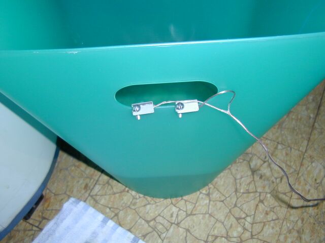


In order to fill up the bucket, I temporarily diverted the pipe coming out the HVAC.

Conclusions
The flood alarm worked for a couple of years without problems and currently is in some box, since the moving changed the needs.At least I know to have it if the need arise again :-)
The most critical part, the sensor, was actually extremely reliable even if so simple.
Only one time I had problems, when a sensor wire broken up, because my bad installation (never EVER use uninsulated pins to attach a cable just because you run out of time !).
But other than that the circuit was really stable and reliable, saving me at least from 3 floods.
As usual, if somebody is interested in the source code, just contact me.
I don't have yet set up a public place where to store the code.
Sunday, October 24, 2010
Repairing a Mickey Mouse Lamp - UPDATED !
My daughter has a nice Mickey Mouse lamp.
We bought it years ago and it worked nicely for many years, until "somebody" connected it to an X10 Lamp module.
After few times, the lamp stopped to work completely.
In this article I'm documenting the repairing process.
We bought it years ago and it worked nicely for many years, until "somebody" connected it to an X10 Lamp module.
After few times, the lamp stopped to work completely.
In this article I'm documenting the repairing process.
Sunday, October 17, 2010
Hacking an Infoglobe - part 5
In order to better test the interface permanently connected to the Infoglobe and free up the breadboard for other experiments, I finally I decided to build an Infoglobe interface on a small experiment PCB, with the technique of point-to-point connection, i.e.wired.
I considered to prepare a PCB but since is still a prototype, is better to build it "fast and dirty", i.e. a point-to-point connection on an experimental board.
Also, I didn't want to spend too much for that, so I looked in the junkyard for components and housing.
I found a nice box I bought years ago for who-remember-now project and I started to collect the components.
I decided that a broken piece of experimental board from Radio Shack was enough for the job, so I collected all the components and started to prepare the first Infoglobe Interface for permanent test.


First I prepared the mechanical part, i.e. drilling the housing to connect a DB9 female, an RJ11 outlet and two holes for the pushbuttons.
With the help of some power-tools I was able to do a "just-barely-decent" work.
No, I'm not really good with the mechanical part.
Then I started to figure out how and where to place the micro-controller PCB.
I picked up a new MSP430F2012 PCB and look in the junkyard to see what I could do.
I started with a straight 7+7 DIL (male and female) but the micro was too hight for the box, so I had to use two 90 degrees 7+7 DIL to obtain a decent hight.
Unfortunately that left very few space for the rest of the components !
Well, will be a very populated board !
With the power tools I beautified (well ...) the broken experimental PCB and started to place some components on.
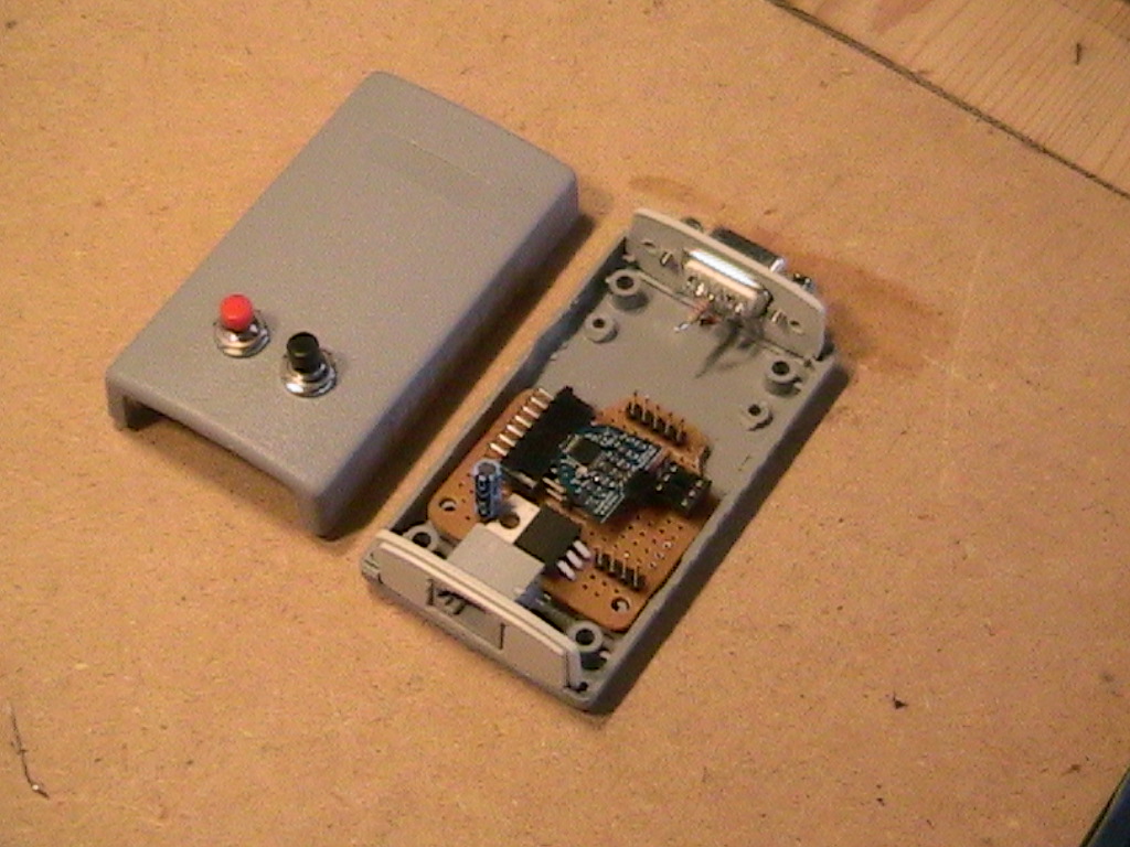
Here the layout of the experimental PCB I'm working on:

A quick note. The current firmware revision of the code, include the reading of the internal temperature of the MSP430F2012 internal sensor, connected to the ADC.This why the two pushbuttons. They select the operating mode.
More details in future articles.
And here some other pictures of the prototype.


I considered to prepare a PCB but since is still a prototype, is better to build it "fast and dirty", i.e. a point-to-point connection on an experimental board.
Also, I didn't want to spend too much for that, so I looked in the junkyard for components and housing.
I found a nice box I bought years ago for who-remember-now project and I started to collect the components.
I decided that a broken piece of experimental board from Radio Shack was enough for the job, so I collected all the components and started to prepare the first Infoglobe Interface for permanent test.


First I prepared the mechanical part, i.e. drilling the housing to connect a DB9 female, an RJ11 outlet and two holes for the pushbuttons.
With the help of some power-tools I was able to do a "just-barely-decent" work.
No, I'm not really good with the mechanical part.
Then I started to figure out how and where to place the micro-controller PCB.
I picked up a new MSP430F2012 PCB and look in the junkyard to see what I could do.
I started with a straight 7+7 DIL (male and female) but the micro was too hight for the box, so I had to use two 90 degrees 7+7 DIL to obtain a decent hight.
Unfortunately that left very few space for the rest of the components !
Well, will be a very populated board !
With the power tools I beautified (well ...) the broken experimental PCB and started to place some components on.
Here the layout of the experimental PCB I'm working on:

A quick note. The current firmware revision of the code, include the reading of the internal temperature of the MSP430F2012 internal sensor, connected to the ADC.This why the two pushbuttons. They select the operating mode.
More details in future articles.
And here some other pictures of the prototype.


Retrofit a small desk lamp with LED
Among the LED lamp kit I had around, there was a 3W Cree Xlamp 7090 with a small power supply.
For a while I kept it mounted it in a cable clipper, glued under a shelf.
Then, after some renovation in the Athena's room, a small desk lamp caught my attention and I decided to retrofit it with such kit.
I removed the original lamp socket and rewired the base of the lamp.
Like the electronic lab lamp I did, I decided to put in the lamp top reflector only the LED with the heat-sink.
The power supply, a very small one, is in the base.
Here some pictures and notes :
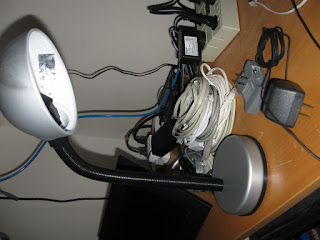
This is the small desk lamp retrofitted with the Cree 3Watt LED.

This is the kit used to retrofit the small desk lamp.
Originally I placed the diffuser/lens, but for this application I removed it since the light is better reflected by the lamp diffuser.

The lamp base opened.
The weight is insulated by a plastic bag.
The base material is plastic, so already insulated.

Here the base emptied.

And here the base retrofitted.
The power supply (on the right) and the new small cable carrying the LED power supply entering in the shaft (on the left).

Here the LED glued on the heat-sink and attached to the original lamp support.

The lamp on. A very nice and strong light.
More than enough to replace the original 40W incandescent bulb.
For a while I kept it mounted it in a cable clipper, glued under a shelf.
Then, after some renovation in the Athena's room, a small desk lamp caught my attention and I decided to retrofit it with such kit.
I removed the original lamp socket and rewired the base of the lamp.
Like the electronic lab lamp I did, I decided to put in the lamp top reflector only the LED with the heat-sink.
The power supply, a very small one, is in the base.
Here some pictures and notes :

This is the small desk lamp retrofitted with the Cree 3Watt LED.

This is the kit used to retrofit the small desk lamp.
Originally I placed the diffuser/lens, but for this application I removed it since the light is better reflected by the lamp diffuser.

The lamp base opened.
The weight is insulated by a plastic bag.
The base material is plastic, so already insulated.

Here the base emptied.

And here the base retrofitted.
The power supply (on the right) and the new small cable carrying the LED power supply entering in the shaft (on the left).

Here the LED glued on the heat-sink and attached to the original lamp support.

The lamp on. A very nice and strong light.
More than enough to replace the original 40W incandescent bulb.
Subscribe to:
Posts (Atom)