Translate

Tuesday, August 26, 2014

Build an airflow sensor

For one of the projects I want/need to do, it was necessary to measure an airflow.
Here how I built a small sensor for that.

The simplest way to do so is to modify a computer fan.
I choose a small brush-less fan (for CPU), with ball bearings.

Circuit


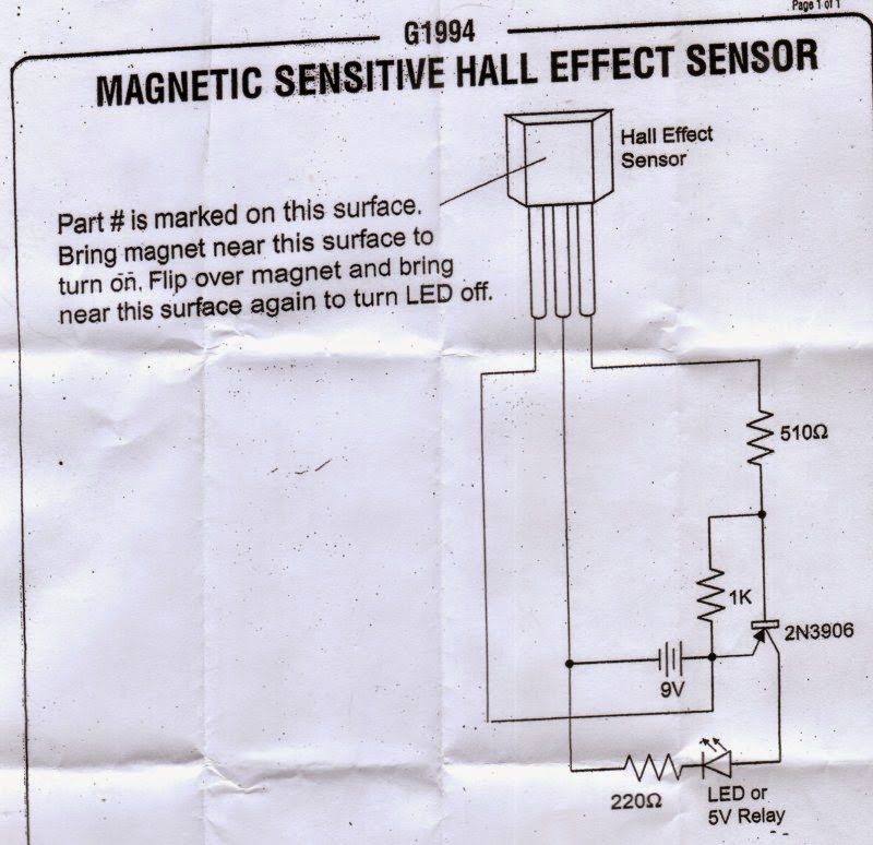
Probably the simplest and safest way to detect the rotation of the blade, is to use an Hall Effect sensor.
The sensor is placed inside the fan case, instead of the original motor circuit.
Below the bipolar Hall Effect sensor I used.  No really need to have a bi-polar Hall Effect, actually a single pole Hall Effect it would work better, but this is what I had around at the time.


Hardware preparation


The first step was to split the rotor from the  main case.
Usually there is a small groove that keep the rotor in place.
On the rotor, in this type of fan, there is the permanent magnet.
It need to be removed.

The motor is usually soldered to a PCB,  just stuck in the plastic case.
With some force is possible to disconnect it.
3 wires, as the original configuration of the fan, are required for the Hall sensor.
Vdd, GND and the output.

Here some pictures of the conversion, starting from the original CPU fan I used (below)


The first thing was to take it apart, removing the motor and electronic.


 Then I glued an Hall Effect sensor close to the shaft, on the base.


On the propeller, I attached two earth rare magnets (very small and very powerful), on the opposite sides.
I left the metal rim inside to facilitate the magnet attach (I also glued them) and to give a little bit weight to the propeller.


The magnets are attached with the poles in the opposite direction, because the Hall Effect sensor I used is a bipolar one, i.e. it needs to "see" a North/South pole change in order to go on, and a South/North pole change to go off.

Here the anemometer completed, attached to a simple circuit to test the Hall Effect sensor.


In the last picture, it is possible to see also the 1 wire temperature sensor  (DS18S20) connected to the cable.
It is the sensor needed to detect the temperature of the air flow.
A simple first prototype , using an MSP430-2013, it was built to develop and test the firmware to read the anemometer and the temperature sensor.


Wednesday, July 2, 2014

Lawn mower - noise and pollution


In the article about the repair of my lawn mower, I mentioned that I can not stand the noise and pollution generated by a traditional gasoline lawn mower.
This article wants to explore little bit more the Pro and Cons to own a cordless (battery operated) electric lawn mower, using material available on the net and my personal experience
And yes, I'm biased toward electric ones for many reasons.

Let's start with a list of the Pro and Cons to choose an electric cordless lawn mower.

Pro
  • is not generating ANY pollution
  • is much less noisy
  • it requires much less maintenance
  • it is more safe
Cons
  • it cost more
  • it has a more limited cutting range
  • it can be stopped more easily
  • it is heavier
Let's discuss the Cons first.

Cost

The cost ... yes, a battery operated lawn mower could cost  more than an gasoline equivalent.
How much more ?
About 1-3 times more on average, BUT things are changing. Newer model of electric lawn mower are coming out with a decent price considered the features.
New type of batteries are used, improving the power and time, more efficient and powerful engines are used and a better blade design is adopted.
For example this new Craftsman 40V Lithium lawn mower has really impressive features considered the price.
My lawn mower is 4 years old. In 4 years the technology improved A LOT !
The future is electric !

Limited range

True with older models, unless to adopt very expensive batteries, a battery operated lawn mower can cut less yard than a gasoline one can do.
On average, a battery charge can last for about 20/30 minutes, assuming to have new/fresh batteries.
If you can cut the lawn on that time you are OK, otherwise you need to recharge it in the middle.
Again the technological improvement in this area is impressive.
Newer type of batteries allows to to extend  the cutting time.

Power

Usually a cordless electric lawn mower is less powerful than a gasoline one.
It can be quite a long and complicate discussion, but it is safe to say that a gasoline lawn mower is usually more powerful. This doesn't means that is a good thing.
Gasoline lawn mower simply use more power to overcame a poor design. More power means more gasoline used and thus more pollution and noise.
In the end the main reason to have more power is when the grass is too thick or too wet.
Blocks of accumulate grass can stop the blade.
The typical answer of a gasoline lawn mower is to increase the power, electric ones are better designed  to reduce the clogging and thus requiring less power.

Weight

The weight of an electric cordless lawn mower can be bigger than a gasoline one.
Up to 80 pounds on older models like mine. The batteries are the main component that determine the weight.
Traditional (and cheap) batteries usually weight a lot. Newer type of batteries are more powerful and last longer (both as life than discharge time).
The weight can be cut in half with newer batteries.


Let's see the Pro now.

Pollution

Well .. this is a BIG issue.
VERY big.
There is a lot to say about this, but let me start with the usual sentence many people say when talking about an electric mower and pollution : "yes, it does not pollute but the electricity you use is produced by plants that pollute !".
Who use this argument should be jailed.
Few points to consider:
  1. Electricity is produced by many different type of plants, some pollute, others not.
    I can even set up a solar charger !
  2. It is much easier and economic to apply filters to ONE plant than to million of machines
  3. Gasoline mowers pollute directly AND indirectly, because in order to produce the gasoline ALL passages generate pollution, from the extraction to the transportation to the local gasoline station !!!
    Is much much more than the pollution created producing electricity.
But "how much" a gasoline lawn mower pollute ?
Well, the answer is really depressing.
Studies showed that the 5% of the USA national pollution is generated by lawn mower !

Each weekend, about 54 million Americans mow their lawns, using 800 million gallons of gas per year and producing tons of air pollutants.

(source http://www.peoplepoweredmachines.com/faq-environment.htm)
800 million gallons of gas per year !
Just to cut grass ???  

There are many studies out there that points out how much pollution is generated by these small appliances (for example http://abcnews.go.com/Technology/story?id=98532).
So much pollution just to have a nice and clean lawn. It is an oxymoron.

And the pollution is not limited to the gasoline burned.
Exists also the pollution created when oil and gasoline are "poured", during the  refilling of the mower. These are pollutant that are going directly in the lawn !

The only pollution that can come from a battery lawn mower are the batteries IF you throw them in the landfill.
For that reason I insist on the need to recycle the batteries !

I use a recycling service company for the batteries : Battery Solution
I usually buy a "iRecycle  kit" for household.
I can not stress enough the NEED to recycle batteries instead than trash them away !
From the button batteries to the sealed batteries, it is IMPORTANT to recycle them.
Don't throw them away !

Noise

A typical lawn mower with a gasoline engine, produce around 88-94 dBA of noise (source the NPC website).
Others sources bring the average lawn mower noise pollution around 90-106 dBA.
Over the 80 dBA the noise is considered unhealthy.

Just to have an idea, take a look to this loudness comparison chart (http://www.dot.ca.gov/dist2/projects/sixer/loud.pdf)
My electric lawn mower is not "silent" but is far lower noisy than the normal gasoline ones.

At 3 feet of distance, I measured 79 dBA.
Measurements done on neighbors lawn mowers at 10 feet (I could not go there and ask "Excuse me, can I measure your noisy piece of junk ? :) ), returned values of 86 dBA!!.
Here a list of measurements done:

  • Craftsman at 3 feet, in front, on concrete (driveway) : 81 dBA
  • Craftsman at 3 feet, in front, on grass : 79 dBA
  • Craftsman at 10 feet, in front, on concrete : 68 dBA
  • Neighbor lawn mower (unknown brand), on front, approx 10 feet (probably more) : 86 dBA 

Just let say that I cut the grass at the same time of my neighbor, and I was barely hearing MY lawn mower !!!
The noise from the neighbor lawn mower, at the other side of the road, was COVERING the noise of my lawn mower, and I was just behind it !

Need more proofs ?

Maintenance

An electric mower has basically 3 components :
  • Batteries
  • Control/wiring
  • Motor
The only component that wear out are the batteries, so it is the only thing to maintain.
Every few years a new set of batteries need to be installed.
Other than that, no gasoline and oil.
A typical gasoline engine has more than 100 parts that can break down. An electric motor has two.

Safety

Gasoline is extremely dangerous.
It can catch fire easily, vapors are harmful, oil is extremely pollutant.
The two technologies (gasoline/electric) have HUGE differences in safety and the most safe is not the gasoline.
The only risk with an electric mower is an unexpected closing of the circuit, reason why usually exists a double switch.
On mine for example, a physical "key" need to be inserted in the control box, where there is the main switch.
Without the key, the switch is disabled.

Saturday, June 14, 2014

Repairing my Craftman electric lawn mower - UPDATE !

Scroll at the end for the update !

One of the things that really irritate me, is the noise and the smell of a gasoline lawn mower.
The tranquility  of a beautiful place is always destroyed when a gasoline lawn mower is turned on.
It's incredible how much pollution and noise one small contraption like that can generate.
Very very annoying.

Thursday, May 1, 2014

iRiver SPINN - replace battery


The iRiver SPINN is a nice MP3 player from iRiver.
Like many gadgets out there it works very nicely until the battery decide that is time for a loooong vacation.

This kind of gadgets have two problems when the battery is involved :
  1. the battery usually is soldered directly to the board
  2. the battery is OEM, in other words, is not "off the shelf" but is usually produced for the specific object
So there are two challenges to overcome trying to have back the unit working.
Open the iRiver and extract the battery, and find a battery replacement.
It seems this project will take quite some time to be completed, mostly because ordering stuff from China can take forever !

Opening the SPINN

February 2014

Fortunately opening the SPINN is more easy than many other MP3 player out there.
There are 3 torx screws to remove.
A T4 Torx screwdriver is required.
Remove the 3 screws, two on the side where the volume and power control are, one close to the USB port.


Once removed the screws, GENTLY, force the side of the plastic back with a small flat screwdriver.


When the cover starts to move, GENTLY with the screwdriver, try to release the latches on the side.
The cover will come out totally.


The next step is to remove the rubber protection of the battery, first lifting the small keyboard connected to the flexible PCB.
The battery is glued to the surface below.
Very GENTLY and slowly, try to detach the battery.  The battery is attached with a piece of tape with glue on both sides.

Once the battery is lose, is possible to desolder it.

Searching for a replacement

February 2014

This is the hard part.
The battery doesn't has any brand or model on it.
Only states it is a 830 mAh battery, with 3.7 Volt.

So, here the data collected about the battery :
  • two wires battery
  • 3.7 Volt
  • 830 mAh
  • shape : square - 4.2 cm side (.5 x 4.2 x 4.2)
  • 5 mm thick
  • ATL
  • code: 414444 A08749330372
I ordered both the models of batteries, mostly because ordering stuff from China can it take forever ... and actually I received the batteries just today !
Very very fortunately one of the batteries was a perfect match for the old one.
Is not the electrical part that creates problems, but the dimensions !
The new battery has to fit the space of the old one !

So the winning model is the number 1.
Inserted the new battery, fit perfectly the space, reconnected (remember the polarity !) and voila' !
The SPINN is back working.
Pay attention to the LCD cable, is enough a light pressure to have some connections loose.

Unfortunately, something went wrong with the battery.
After few hours of charge, the new battery was dead !
Defective battery ? Wrong type of battery for the charger ?
Charger damaged ?
I hooked up the second battery and the SPINN was back alive again, but now I have to do some tests to see how the recharge process affect the new battery.
If also the second battery will die, I have to try to figure out what the problem is.
Sure the second battery mechanically doesn't fit the SPINN space. I need to order a new battery again, another month and half waiting if I order form the same place.
Or probably is better to look on other places ... another search is required.
Stay tuned !


Sunday, April 13, 2014

Beagle-Board - Beaglebone Black - re-flash it

Yes, OK OK, another post on internet about how to re-flash a Beagle-board Beaglebone black (BBB).
Why ?

Well, I needed to bring back to the origins my BBB and I found tons of instructions if you have Windows or Mac and some contradictory or incomplete instructions for Linux.
So, here my brief note to describe how to re-flash a BBB.

This procedure should be used in order to install the image on the BBB internal memory.
Basically the image will be copied on the internal memory.

Download the image

The image to download MUST BE one for the flash.
Normally is called BBB-eMMC-flasher-yyyy.mm.dd.img.xz from the Beagleboard latest images  link.
oh wait .. WHAT image ?

Well, I wanted to restore the original configuration as when I received the board, so Angstrom.

Prepare the image

On the net there are many places that describe how to do that under Window or Mac OS.
I'm using Ubuntu 10.04 LTS. Any versions however should do.
It is needed :


  • Archive Manager
  • Disk Utilities
  • dd


With the Archive Manager extract the image from the compressed file.

Load the image on the card 

You will end up with a file approx 3.6 Gbyte, so better to use at least a 4 Gbyte micro SD card or better, 8 Gbyte one like I did.
Put the micro SD card in a reader and connect it to the USB port.
Using Disk Utilities identify the added driver, it will be something in the range /dev/sdx.
Also, using the Disk Utility, unmount any partition eventually present on the microSD card.

Open a terminal, go in the directory where is contained the image file and in sudo mode type this command :

sudo dd if=BBB-eMMC-flasher-yyyy.mm.dd.img of=/dev/sdx bs=1M

where yyyy.mm.dd is the part of the image name with the date and x is the correct driver associated with the inserted SD card.
BE VERY CAREFUL in this phase.
A misspelled driver name can format something else !

After few minutes the SD card will be ready.

Flashing the board


Time to flash the board.
ATTENTION !  The procedure can take quite a while !
Allow at least 30 to 45 minutes ! It could take longer though.

Follow these steps :


  • Be sure to have the board powered down
  • Remove any cape and USB stuff
  • Insert the microSD card in the microSD card slot
  • Push down the S2 button
  • Power up the board KEEPING PUSHED S2
  • When the 4 LEDs goes on, release S2
  • Some activity on the LEDs will indicate the loading process
  • Wait until ALL the 4 LEDs  are back ON - steady ON
  • Power off the board
  • Remove the microSD card
  • Reconnect cape and USB stuff if you have it
  • power up again the board

I found in my case, that it is important to have the "bare" board, no capes or USB stuff attached.
I had a USB dongle for an external wireless keyboard and I was unable to flash the NAND.
After removing LCD cape and USB dongle, I was able to flash the NAND without any problem.

Now I have the board running happily with full X server on the LCD.

Hope this article can help somebody

Sunday, March 23, 2014

iFood - bread Bodini

Well, technology is my world, but I'm a human being  too, and one who loves to eat.
This blog is technical oriented, preparing food is an art but involve technology too ... OK OK, today I'm feeling to share one of my recipes.
When I have time or when I'm in the mood for bread or pizza, the only way to satisfy such mood, is to prepare the bread or pizza by myself.
I love to cook many other things, on my Pinterest table "iFood" i show something ... if you are curious enough to see that :)

Bodini's bread and pizza recipe

Example of bread obtained with this recipe

Tools

  • Bread machine.
    To prepare the dough, use a bread machine.
    Nothing special, almost every generic low cost bread machine will work.
    Just be sure that it can prepare the 2 pounds loaf. Usually such kind of bread machine cost around $40.
  • 2 cups Pyrex to measure liquids.
  • Set of measurement spoons, from 1/4 tsp to 1 tbs
    tsp = teaspoon
    tbs = tablespoon
  • Set of “cups” to measure the flour. Usually these sets goes from 1/4 Cup up to 1 Cup
  • wooden mattarello
  • dough cutter 
  • sprayer for water
  • round cutter (for “panini”)
  • rectangular nonstick baking trays for the bread.
  • Round nonstick baking trays for pizza. Much much better if they have holes, like this one :

Bread/Pizza dough

Ingredients

Ingredients for 20 “panini” or 4 pizzas :
  • 1 ¾ cup room temperature water
    It is strongly suggested to use filtered water, left in a jar for at least a night.
    Impurities will be on the bottom and the water will be at room temperature.
    Never underestimate the quality of the ingredients, especially the water !
    Water with chlorine or other impurities will make difficult to the dough to raise and will leave a sour taste !
  • 2 tsp fine salt
  • 2 tsp sugar
  • Extra virgin oil
    - Bread : pour enough oil to cover ¾ of the water surface
    - Pizza : the oil have to cover the entire water surface
  • 6 cup “normal” flour ( 00 )
  • 3 tsp yeast for bread machine or fast raising

Preparation

Put in the bread machine bake pan the ingredients, in this order :
  • water
  • salt
  • sugar
  • oil
  • flour (level it )
  • yeast


Set the program “only dough”, NO BAKING !
This is IMPORTANT because the quantity of the ingredients is above the baking capability of the bread machine !!

Bread preparation


When the dough is ready in the bread machine, remove it from the baking pan and put it on a table.
In order to prepare “panini”, use the “mattarello” to flat the dough.
Flat it at least to reach ½ inch thick.
Then use a round cutter to cut at least 10-14 “round panini”.
Put them on a nonstick baking tray (is possible to use also the pizza round baking tray).
Leave some space between the panini since they will raise a bit and leave them on it at least for 1 hour (don't go over 2 hours !)
The left over dough can be put together and flattened again, then cut it in triangles and then roll the triangles to form a mini roll.
At the end of the raising time, spray the bread with water and put them in the per-heated oven at 400-405 degrees Fahrenheit for at least 18 minutes.
Check sometime the bottom of the bread. If is yellow/brown is ready.

Remove it from the oven and left it to cool down at least for an hour before to eat it.
The best way to cool it down, is to remove the bread from the baking tray (use mittens or oven gloves, it will be HOT !) and put it in a basket.

The best way to taste it is to cut it in half and then put some salami or cooked ham, a little bit of mayo or some cheese (swiss cheese will be great).

It is possible to put the bread in the freezer.
Put it in small quantities (4 to 6 paninis) in a 1 gallon freezer plastic bag. Gently squeeze out the air before to seal it.
The bread will last at least two to three months.

To re-heat it, pre-heat the oven to 350 degrees Fahrenheit, then put it still frozen (out of the bag !) for at least 8 to 10 minutes. Will be like just made.

The bread will last at least a couple of days if not put in the freezer.


Pizza preparation


When the dough is ready in the bread machine, remove it from the baking pan and put it on a table.
Create a big roll and divide it in 2, 3 or 4 pieces.
2 pieces if you like a “soft pizza”, 3 for a normal pizza, 4 for thin and crunchy pizza.
The best result is with 3 pieces.
It is also important to considering the type of topping.
Cheese topping will require short cooking time, topping with vegetables or other ingredients will require more time.
A thin crust will be OK for cheesy pizza.
Thin crust will cook MUCH faster than normal crust ! Remember that !

Using the “mattarello” flat each piece in a round shape.
Spray with flour and turn upside down the pizza during this stage, multiple times.
The dimension of the pizza has to match the round baking tray and thus will determine the “thickness” of the pizza.
Put the flatten dough on a round baking tray.

With a spoon put the basic topping (see below) over the pizza. It must be spread uniformly.
When the oven is per-heated (again 400-405 degrees Fahrenheit) place the pizza in it.
The baking will happens in two phases.

  1. Phase one
    Put the pizza with the basic topping on it in the oven at least for 9 minutes (thin pizza) to 12 minutes (thick pizza).
  2. Phase two
    Remove the pizza from the oven and spread it uniformly with a lot of shredded mozzarella cheese.
    Put the pizza back in the oven for at least 9 minutes more.
    Check the mozzarella ! When it start to become yellow/orange the pizza is ready !!
    If the mozzarella does not have yellow/orange spots, then is NOT yet ready !
    Don't over bake it.


Topping


How to prepare the basic topping for almost every type of pizza.
In a container, pour the content of a big can of crushed tomato.
Be careful to use ONLY crushed tomato ! Not crushed tomato with basil, or garlic, or other stuff in it.
Then add some extra virgin oil (a couple of table spoon), salt (two or three tea spoon), sugar (1 or 2 tea spoon), oregano (as much as you like, however too much will make the sauce too sour).
Mix it very well.
These quantities are enough for 4 pizzas

For 4 pizza, you will need also at least 8 to 10 cups of shredded mozzarella.
More if you like a “cheesy” pizza.

Sunday, March 2, 2014

Quality time with my daughter

My daughter this year choose to do something different from the usual "biology" science fair project.
She choose to build an electric motor and do some tests to see how is possible to improve the conversion of electricity into kinetic energy.
So it was natural my direct involvement in this.

The science fair project had some specific guidelines and "things to do", but from a more practical point of view, the first thing to do was  to build a basic electric motor.
We found  a lot of suggestions on the net about how to do so. In the end the choice depended about the availability of material and simplicity of building.
Here a brief video showing the motor running.


Oh ... she won the Third place for her category at school :)
She also participated to the regional science fair. Unfortunately the motor broke down during the presentation (see notes "Problems" at the end of this article)

Third place for the category

Building a motor

There are many ways to build an electric motor and there are many types of electric motors.
There are AC motors and DC motors.
The object of the experiment was to show how some components of the motor could affect it's performance, when changed.
So we picked up one of the basic-simple type of electric motor, a DC static magnet rotor motor.
The type of motor we wanted to build, had fixed magnet on the moving part (rotor) and an electromagnet on the base (stator).
Many commercial motors have the electromagnet on the rotor and the fixed magnets in the stator, or both electromagnets for rotor and stator, but they are more complex since it must exists a way to bring the electricity on the rotor, a moving part.

Principle


The type of electric motor we choose to build  is extremely simple.
The idea is to have two or more magnets on the rotor. The magnets need to be "paired", i.e. they need to be aligned to themselves.
This simple schematic can help to understand the principle.
When a magnet is close to the Reed switch (a switch activated by a magnetic field) it powers the electromagnet.
The electromagnet generates a magnetic filed with the same polarity of the magnet glued to the rotor, "kicking" it and thus forcing the rotor to spin.
As soon the rotor starts to spin the magnet close to the Reed switch is going away, thus the electromagnets cease to work.
The rotor however continues to rotate for mechanical inertia until the sequence restart, i.e. magnet close to reed switch, electromagnet activated, kick to the other magnet, and so on.

There are some constrains :
  • the magnets need to be glued on the rotor facing with the same pole
  • the position of the Reed switch must be as much as possible aligned with the position of the electromagnet
  • the distance between the Reed switch and the magnet on the rotor is critical. If too far the Reed switch is not activating.
  • the distance between the electromagnet and the rotor is critical too. If too close the magnet on the rotor "attach" to the electromagnet when it is disabled.


Rotor

The rotor is the part of the motor that "rotates" and, for the experiment, is the part we decided to change in order to evaluate the performance of the motor.
The rotors were  built using an empty thread spool, magnets and office pins.
Two or more magnets (always in pair) were  glued on the spools and two pins were glued on the spool central hole to form the axe.


Gluing the magnets on the spool

The spools with the inserted pins to form the axe

We chose to orient the static magnets on the rotor with the South pole facing out, mainly because the RPM meter sensor works on the South pole of a magnet.
We used a simple app for a smartphone to determine the magnet polarity.

Stator

The stator is, for our purposes, everything around the rotor.
We used a wooden base and wooden blocks to build the support for the rotor, the electromagnet, the Reed switch and accessories (main switch, RPM meter, ecc.)

The basic components of the stator, a wooden base and wooden blocks

The electromagnet was connected to a battery and a Reed switch.
The Reed switch is necessary because we need to turn on and off the electromagnet in order to generate a magnetic field only when a rotor's magnet is close by.

Electromagnet

We needed something metal and an insulated electric wire in order to build a coil around the metal part.
Since we used  using small voltage for the project (up to 4.5 Volt) we needed a lot of wire.
We used a nail as metal core of the electromagnet, with the wire coiled directly around it.
We used a drill to facilitate the winding of the wire around the nail

Electromagnet, Reed switch and wooden blocks

Prototypes

Two prototypes were built.
The first one was built mainly to prove the concepts and experiment positioning the components.
The second prototype was the one used to actually perform the test and it was built differently, since we learned from the first one what NOT to do.

First prototype


The first prototype was built positioning the electromagnet on the top of the rotor and the Reed switch fixed at the base.
The idea was to have the Reed switch easily glued at the base and position the electromagnet on the top, it was easier to adjust the distance between the electromagnet and the rotor.

The first prototype
The first prototype was working however it had many problems, like :
  • the electromagnet was moving, required more strong holding
  • the distance between the rotor and the Reed switch was fixed
  • it was difficult to change the rotor
  • the rotor was not strongly hold on the wooden blocks
  • the electromagnet was too weak
  • the voltage used was too high
In the end we realized it was better to rebuild it with different principles.

Second prototype

The second prototype was built with  the idea to be able to easily change the rotor and position the electromagnet/Reed switch more easily.
The second prototype layout

A new electromagnet was built, using a 3 inches nail and almost 250 feet of wire, held by a wooden block carved to the shape of  the electromagnet.

The electromagnet holder, a wooden block carved to the electromagnet shape

The new layout included also a better support for the rotor and the attachment of an RPM meter.


The second prototype used for the test. The RPM meter is shown on the  lower right corner

The RPM meter


In order to evaluate the motor performance, we decided to use the speed of the rotor.
To measure the rotor RPM we needed a tool, an RPM meter or 'tachometer'.
So I built an easy tachometer using one of the boards I had around.

The experiment

At this point we had everything ready for the experiment.
We had a motor base, capable to support a rotor and an RPM meter.
We built 5 different rotors, changing the type of the magnets and the number of the magnets.

  • Rotor 1
    Two ceramic 0.5 inch magnets - Weight : 12.5 g 
  • Rotor 2
    Two Neodymium 0.5 inch magnets - Weight : 20.9 g 
  • Rotor 3
    Two Neodymium 0.2 inch magnets - Weight : 12.7 g 
  • Rotor 4
    Four ceramic 0.5 inch magnets - Weight : 16.4 g 
  • Rotor 5
    Four Neodymium 0.2 inch magnets - Weight : 14.4 g
We decided to proceed in this way :

For each rotor, we choose to perform the test 4 times.
During each test, we set up the RPM meter, let the rotor run for about a minute to "stabilize" the system and then start a 2 minutes timer.
Every 10 seconds we took a reading from the RPM meter.
In this way we ended up with 5 different set of data, one for each rotor.

Capturing the data

Setting the RPM meter

Reading the RPM meter every 10 seconds
From the readings we created 5 graphs to better compare the performance using different rotors.
Here they are :


All the graphs were built using the same scale, so it was possible to compare them directly.
Looking at them resulted that indeed changing the type of the magnet and the number of magnets, the motor had different performances.

Problems

We also experienced a problem.
After building the second prototype we started to collect data for the experiment.
However some rotors had problems. They were spinning at very low RPM and often they were not spinning at all.
We checked the motor and apparently everything was OK .. only apparently.
In the end we discovered that the Reed switch was defective or damaged somehow and it was not always capable to react to the magnet on the rotor.
We decided to substitute the defective Reed switch with a new one, and all the rotors were behaving as expected.

The same problem happened later, during the regional science fair.
The Reed switch broke down again.  The very probably cause of the broke down is the spike of voltage generated by the electromagnet when the Reed switch opens.
Hooking up an oscilloscope we saw spikes up to 250V. On the long run, spikes like that can warm up the metal of the contacts, bending them and leaving the Reed switch unable to operate correctly.
i.e. on the long run the Reed switch mechanical characteristics are compromised by the sparks generated by the electromagnet generated spikes.

The spike in full view - each vertical block is 50 V

A detail of the spike

The poster


Here a couple of pictures of the poster my daughter prepared for the presentation.


Saturday, December 28, 2013

Chromecast - quick review

I recently bought a Chromecast device to test.


I already have an Android based "pen-USB" streamer connected to my TV and I was curious to see how a different system was working.

Here some impressions.

Opening


The package itself is quite fascinating.
The device is quite small, actually little bit smaller than the USB Android pen device I'm currently use.
In the box, well packed, there is the device, a power supply, a micro USB cable and an HDMI extension cord, just in case is not possible to connect the device directly to the TV.

Installing

Installing the Chromecast device is quite straightforward.
Just plug it in into a HDMI port on the TV and connect the power.
Some TV have an USB hub integrated, so in this case will there no need for the external power supply.
After a few seconds a screen will appear on the TV.

At this point the best way is to use an Android system (or iOS) and follow the instructions.
A Chromecast application is installed on the smartphone/tablet and from there is enough to follow the directions.
The required time to install Chromecast is around 5-10 minutes top.

Use


One thing must be understood immediately.
Chromecast is working with specific stream services !
In other words Chromecast can stream ONLY services that have an "app" for Chromecast.
Chromecast is NOT :
  • a generic Android system connected to the TV
  • a relay of the screen of your phone or tablet
  • a stand alone computer
Currently is possible to stream from YouTube, Netflix, Hulu, Pandora and few other services but a lot of people is working to bring more apps to Chromecast, to allow more streaming.
The quality of the streaming  is very very good actually, much more better than my USB pen-based Android streamer and also the WiFi management seems better and more reliable than the USB Android pen-based streamer.

The connection to the streaming servers is totally transparent, i.e. no need to set up accounts or passwords. So if somebody with a smartphone has a subscription to some service (like Netflix)  the Chromecast will use that to be connected.

Problems


Well, actually there are few problems, but I'm quite sure they  are depending about my particular configuration of the network.
On my network I have almost everything  with a fixed IP. I do have a DHCP server but the majority of the appliances have a fixed IP (for many reasons).
Chromecast currently is NOT supporting the fixed IP configuration.
So sometimes my DHCP server assigns an address that for some reasons is not working well, leaving the  Chromecast not working. 
On "standard" domestic/consumer oriented networks, where everything is under DHCP, there are actually no problems that I'm aware off.
Another issue is the impossibility to easily stream from a local server.
It is possible to have some streaming done from the phone but there is not an easy way to do so yet.
I'm sure it will be fixed for the future.

Conclusion


Well, for the price I would say that is a "must to have" little device.
Is NOT meant to substitute a self-contained Android terminal connected to the TV, but is incredibly useful to see on TV the most popular streaming using a smartphone or tablet as "intelligent remote".
While watching a streaming the smartphone or tablet remains free to do other things or look for other programs.
And is fun too. Friends with a smartphone/tablet (Android or iOS) can connect to the Chromecast ( after installing the application on the smartphone/tablet) and show their stream selection to everybody.

Update


Just a quick note.
Chromecast can be used also with Apple products.
i.e. is not necessary to have Android smartphone or tablet in order to use Chromecast.
It is also possible to stream from any PC/Mac running Chrome (via  a plug-in for Chromecast) but honestly if you are already in front a computer, is not really important to stream on a TV (my opinion of course).

Tuesday, December 24, 2013

An anti-spam device - introduction

Notes about the feasibility of an anti-spam phone calls device.

Spammers.
Any day there is always somebody, or somewhat, that place a call to advertise the last offer for a credit card, or to sell the latest life insurance or who knows what else.

Unless to pay for some provider options, usually expensive, the main weapon against these pests, is the caller-ID.

Often is enough to see the number to identify the caller as spammer.
But sometime the number is "local", one of the many tricks spammers use to make more hard to identify a spam call.
Instead to use a 1 800 or 1 888 or other "free" or "commercial" numbers, they use local numbers, to trick the users.
Because of that, the second weapon against these pests, is the answering machine.
With that, you can "screen" the incoming call and identify a spammer or a real call.

The third weapon is our hand.
Everytime an incoming call is recognized as spam, is enough to off-hook the handset and then on-hook it, just to avoid to have the phone ringing and/or a useless and annoying message be put on the answering machine.

But since I'm lazy ... why don't build an appliance capable to do what I normally do ?

The idea is to have an appliance capable of screen the incoming calls and eventually close calls coming from known spammers.
It can not prevent the 100% of spammers to annoy with the calls, but it can limit the disturb.

How it works

The idea is quite simple.
Everytime an incoming call arrive, the system reads the caller ID and compare it with an internal data base.
If the number or name is recognized, the system will pick up (off-hook) and immediately put down (on-hook), closing the incoming call.

Or alternatively, the system can go off-hook, play a message and then on-hook.

If the number is NOT recognized, the system will wait for the user to push a button.
The last received number will be retained, so at any moment pressing the pushbutton, the number will be stored and put in the search list, if not already present.
From the user perspective, if a call is coming from a spammer, will be enough to press a button to let the system to remember the offensive number.
After that, every call coming from that number will be answered by the system.
Of course the system is not 100% accurate because unfortunately some calls doesn't have any caller-ID associated or they have a generic "private" or "unknown" indication.
Some policies are necessary, with a set of limitations, to deal with these special cases.


Specifications

The system will be capable of :
  • be connected to a PSTN phone line, POTS interface,  in parallel 
  • be capable to recognize when an incoming call happens
  • be capable to read the caller-ID of the incoming line
  • to search in a database if the caller exists
  • be capable to simulate the off-hook / on-hook and eventually to send a audio message on line
  • be capable to "edit" the database contents (for example to remove a user put in black list)
  • store information about incoming calls (date, hour, lenght of the call, ecc.)
  • (optionally) have a LAN interface for management/remote administration

Architecture


The system is built around a processor and logical modules.
Every module describe the functionality, not how it is done.


Ring detector

The ring detector circuit, alerts the processor about an incoming call. 

Caller ID reader

The caller ID reader, is sending to the processor the data of the incoming call in ASCIIZ format.

Off-hook/On-hook circuit

The Off-hook/On-hook circuit allows to simulate the handset operation, forcing the line off-hook and on-hook.

Input/Output

At least a display and small keyboard will allow to interact with the appliance.
Depending the processor/platform used, a remote connection (serial/LAN/wireless/ecc.) could allow a computer to extract data/edit the database 


Possible systems

There are many different approaches in order to build such appliance.
The operations to do are simple enough to be executed by a small processor.
Any MCU capable to handle few I/O and having some comunication capabilities, is suitable to be used.
For example a PIC or Arduino or MSP430 can do the trick.

I have around a nice candidate for such project,  the Olimex board with the MSP430f169, that also has a SD card reader/writer, in order to store the phone numbers.

An Arduino board is probably the most efficient solution.

Another approach, is to use a ready made high level system, using maybe embedded Linux as main system.
For example the FriendlyARM board, that supply the processor/memory/user input/display functionality or a Beagleboard or similar card.

Another  board, connected using an RS232 port and I/O, can provide for the Caller ID reading capability, line detection and off-hook/on-hook functionality.

It is indeed quite an overshoot to use a board like the FriendlyArm, but assuming to have the development environment ready, it should be much more easy to build the system.
With such board become also feasible to create an interface to access the data remotely via web.

In any case a board with the POTS interface needs to be built and then interfaced to the system.
An old caller-ID kit is used for the caller ID functionality.


Mc145447 demo board

Centuries ago I bough a kit based on the Motorola MC145447 chipset.
This chip-set allows to decode the incoming caller-ID frame and extract it in ASCIIZ on a RS232 line.
The chip set also provide the ring detection circuit, in order to know if a call is incoming.

Here the schematic of the ITU kit based on the MC145447.

Note that this chip-set is long out of production, but amazingly is still available !


POTS interface

Test #1
A board capable to handle all the POTS operation can be built, starting with the caller ID circuit.
Here a schematic of a test circuit to do the first experiments :

   antispam_test1.png


The transformer is used mainly to give the correct load when simulating the off-hook, but in future it is possible to use it to send audio messages on line.
For example is possible to simulate the "disconnected  tone" usually sent by the telco provider, in the hope that the calling system will stop to place calls.

Or, just to vent out some stress, to play bad messages toward the spammer :-)

The first tests are done on a breadboard with recycled components.
To the ITU Caller ID kit (the green PCB on the breadboard)  I attached an old modem transformer and a reed relay.
A push-button gives the signal to activate the relay (it will be replaced by a MCU I/O).

The first tests are positive. The circuit is connected to the phone line in parallel and when the phone is ringing, pressing the push-button the call is taken and then released, simulating the off-hook/on-hook operation.
Attaching an audio source to the other side of the transformer (see the plug) is possible to hear it on the remote phone when the system is on off-hook.
In the picture is visible also the Olimex board.

 
Test #2

The next step is to start to integrate the POTS interface toward the micro, in this case the MSP430F169.
The breadboard is more populated, with the addition of a voltage regulator, a more easy to use power switch and the Olimex board, with some signals hooked.
Also some signals from the MC145547 chipset are brought out.

Here a new schematic.


and a picture of the new populated breadboard.


For the moment the MC145547 chip (green board) is interfaced to a normal RS232 connector.
Note the Olimex board with some signals brought out.

The Olimex board will be usually powered by the JTAG, only for tests it can be powered (as in the picture) from the 5V regulator.

This is what I did so far, a very quick prototype to test the feasibility of the idea.
The next step is to build a more reliable circuit and choose the final board.
In the example, the Olimex board with the MSP430f169 was used but probably an Arduino or something Linux based it should be better and more flexible.
As usual I have to wait to find the time and resources to do it ...